Volume IV PART 1 : MASTER PROGRAM SPECIFICATION (excluding Program Trials System) CONTENTS 1 THE INPUT/OUTPUT CONTROL ROUTINES 1.1 Introduction 1.2 The Intercode Read/Write Instructions 1.3 The Intercode Open File Instruction 1.4 The Intercode Close File Instruction 1.5 Rewind Magnetic Tape File 1.6 Magnetic Tape Alignment 2 OVERFLOW ALARM 2.1 Conditions Producing Overflow 2.2 Procedure Following an Overflow 2.3 Master Program Action 3 LOCKOUT ALARM 3.1 Conditions Producing an Alarm 3.2 Procedure Following the Alarm 3.3 Master Program Action 4 LOG ROUTINES 4.1 The Means of Communication 4.2 The Presentation of Options 4.3 The Record of Activities 4.4 Date and Time. 5 OPERATOR INTERVENTION ROUTINES 5.1 The Means of Communication 5.2 Operator Commands 5.3 The Operator's Choice of Options 5.4 Acting on Operator's Commands 6 PRIORITY CONTROL ROUTINES 6.1 Priority Arrangement 6.2 Purpose of Priority Control Routines 6.3 Action when a Route is found to be Engaged 6.4 Action when an Operator Decision is Awaited 6.5 Action when a Route becomes Available or an Operator Decision is Made 6.6 Timing Facilities 6.7 Request for Use of Log Routines 6/5 Amendment No.32 November 1966
Volume IV 7 ALLOCATION AND LOADING PROCEDURES 7.1 Purpose of Allocation 7.2 Facilities Requiring Allocation 7.3 Maintenance of Records of Available Facilities 7.4 Request for Allocation 7.5 Procedure 8 THE ABANDON ROUTINE 9 STORE DUMP ROUTINE 9.1 Purpose and Scope 9.2 Data 9.3 Results 9.4 Procedure 9.5 Operating Notes 10 ON LINE STORE POST MORTEM 10.1 Purpose and Scope 10.2 Data 10.3 Results 10.4 Procedure 10.5 Operating Notes 11 UPTIME CARD ROUTINES APPENDICES A Equipment and Store Space Required by the Master Program. B Master Program Operating Instructions. C Layout of Store Dump Tape Heading Blocks. D Layout of Online Store Post Mortem Printout. Amendment No. 4/41 6/8 March 1968
Volume IV INTRODUCTION TO THE MASTER PROGRAMME This volume contains a complete specification of the set of standard routines known collectively as the Master Programme. The general principles and aims underlying the use of the Master Programme are briefly introduced here, to provide the foundation prerequisite to a more detailed understanding of individual routines. The Master Programme should be seen as a means of increasing computer efficiency. In this context efficiency means deriving the maximum benefit from the potentialities of the computer system as a whole. This implies effective deployment of human effort as well as full use of machine capacity. The central processor, or computer proper, is the part of the system which affords the greatest saving of time and money, and is therefore the part towards which efforts at full machine utilisation should primarily be directed. Peripheral equipment depends on mechanical parts and works much more slowly than the central processor, which is wholly electronic. The practical effect of this difference in speed constitutes one of the main barriers to efficiency: the central processor is often in use for only a small fraction of the time when a job is being run. Hardware sophistications such as concurrent working go some way towards solving the problem; but the characteristics of the individual job limit the use that a single programme can make of this facility. For example, successive calculations may each require a large amount of one type of data; and if calculation cannot begin until the whole block has been input, the computer may be held up. Time may also be wasted when operator action is awaited, for instance when he has to make a decision or when stationery needs replenishing. It is an obvious advantage in such cases if the machine is able to carry on immediately with some other job. The method of working adopted, whereby two or more programmes are held in the store at the same time, control being passed from one to another as necessary, is known as multi-programme running or Timesharing. The facilities necessary to implement Timesharing include a system of programme priorities to enable the interchange of control to be methodically effected, and some means of keeping each programme distinct in the store and free from any possibility of interference by other programmes. These facilities can conveniently be provided by standard routines held in the store as part of the Master Programme. As another step towards increased efficiency, it is desirable to avoid duplication of effort, particularly in programming. All programmes have certain basic tasks in common. The routines to execute these need only be written once if they are held in a standard form and made available to any programme. Main areas in which this type of saving can be made are control of input and output, and communication with the operator. Amendment No. 27 6/1 February 1965
Introduction (Cont'd) Communication warrants additional consideration, since standardisation here also has the important effect of making the operator's job easier and less prone to error. If the programmer were to write special routines for communication as part of each programme, comprehensive operating instructions would be necessary, since operating procedures would vary considerably from one programme to the next. Three refinements have been mentioned as contributing significantly to increased efficiency: Timesharing, Input and Output control, and standardisation of communication. The Master Programme consists of standard routines to provide these basic facilities and to attend to some of the many miscellaneous or 'housekeeping' tasks involved in coordinating and recording the computer's activities. It is therefore necessary for the Master Programme to be kept in the store during all normal running of programmes. This introductory description serves only to outline the purpose of the main routines. Within this framework, Master Programmes can be produced with varying degrees of sophistication, by the addition of certain optional facilities. According to users' requirements and available store space, any of these facilities can be included or omitted in order to suit the Master Programme to the particular installation. Optional facilities are noted where appropriate in Part 1 of this volume. For a summary of facilities offered by the fully reduced Master Programme, with all optional facilities omitted, see Part 1, Appendix B.1. Amendment No. 27 5 6/1 February 1965
Section 1 1 INPUT/OUTPUT CONTROL ROUTINES 1.1 Introduction The Input/Output Control routines contain the Computer code expansion of the Intercode Group 4 instructions. Some preparatory work is carried out in the object programme by instructions generated by the Translator, but the bulk of the routines are situated in the Master Programme area of division 0. The Master Programme makes no provision for non-standard paper tape and cards (e.g. 5-hole paper tape, binary cards). 1.1.2 Computer Code Actions Certain computer code actions used are described below: 1. Test Route: This instruction is used to test the availability of a specified route. If the route is not available, one of the following alarms is set: (a) Route closed: This indicates that the route requires the attention of an operator or engineer before it can be used again. (b) Route engaged: This indicates that the assembler is already occupied in carrying out a previous instruction. (c) Doubtful block: This occurs if any fault was detected in the transfer of information during input or output. If this alarm is encountered, corrective action must be taken on the last route to use the assembler. The Master Programme maintains a record of the last route used on each assembler. The alarm is directly generated by parity failure between the magnetic tape assembler and deck and by parity failure on paper tape. Other faults close the channel, and the doubtful block alarm is generated when the 'Assembler Reset' key is operated. In the following account of the computer code expansion of the Intercode Group 4 instructions, the references to action taken when a doubtful block alarm is discovered, relate to action taken on the route under consideration, although the alarm may have been discovered when testing another route using the same assembler. (d) Warning of end: This alarm represents various conditions according to the peripheral equipment on the route being tested.
Section 1.1.2 (Cont'd) 2. Interchange Area Addresses The Intercode 'Read' and 'Write' instructions make reference to areas of the store allocated as input or output sections. The computer code 'Read' and 'Write' instructions make reference to areas of the store allocated as annexes. To avoid the need to transfer data between sections and annexes, the facility to alter the function of an area is used. The annexe and section interchange their functions, becoming section and annexe respectively. This is achieved by means of area modifiers, which are special compartments in locations 64 - 127 of division O of the store, in which are held the start location of all annexes and input or output section. The Loader routines (see section 8) stack into each area modifier, the starting locations of the annexe or section to which it has been allocated. The method of interchanging the functions of an annexe and an input or output section is to interchange the contents of the associated area modifiers, this being done by a single instruction, 'Interchange area addresses' (Action 1/0/5, see Volume I, Part 1 - 16.1.2). On a machine with Fast Channel Control, Action 1/0/3 is not permissible. 3. Read One Block on Route R One block of data is read into the area specified by the contents of the area modifier in compartment 64 + R. 4. Write One Block on Route R One block of data is written from the area specified by the contents of the area modifier in compartment 64 + R, except in the case of routes on the Paper Tape Output Assembler, and the typewriter and paper tape punch routes on the General Purpose Output Assembler. In the former case one word is output from a fixed location (154) of the store, while in a latter, one character is output from bits 33-38 of the word specified by (64 + R). 1.1.3 Magnetic Tape Control The main functions of the magnetic tape control system are: 1. To ensure that a program receives the correct input tapes; 2. To ensure that no information is overwritten until it has become redundant. The tests made by the Input/Output Control routines are outlined in section 1.3.1. Amendment No. 29 6/2 August 1966
Section 1.2 1.2 The Intercode 'Read' and 'Write' Instructions The expansion of the Intercode 'Read' instruction includes: 1. Test that the information has been read correctly. 2. Check the information in the annexe. 3. Make the information available to the programme, if the above check has been successful, by use of the 'Interchange area addresses' instruction. 4. Initiate a 'Read' order to bring the next block of data into the annexe. The expansion of the Intercode 'Write' instruction includes: 1. Check that the last block of information was written correctly. 2. 'Transfer' data from the programme output section to the annexe by means of the 'Interchange areas addresses' instruction. 3. Initiate a 'Write' instruction to output the block. Further details are given below. 1.2.1 Magnetic Tape 1.2.1.1 Output The subroutine controlling writing performs the following tasks: (i) Tests the route (ii) Writes serial numbers (iii) Initiates the 'Write' instruction (i) Test Route 1. Route Closed: The Master Programme types a warning of the closure which is repeated every three minutes. 2. Route Engaged: The Master Programme passes control to the next programme in the priority queue. A link is left which enables this same route to be re-tested when an interruption occurs.
Section 1.2.1 (Cont'd) 3. Doubtful Block: The doubtful block may have been caused by an imperfection on the tape. The Master Program therefore attempts to bypass any imperfections by overwriting the last block with one which differs from it only in having three faulty block characters, (Control quartets of 5 and basic quartets of 15), as the most significant three characters of the first word. The remaining characters are the least significant two characters of the block serial number of the doubtful block), and "1" in the second word. This block is repeated up to six times augmenting the second word by one each time. If during this process the doubtful block alarm ceases to be generated, the original block is written and a report typed. This report may be suppressed or given after twelve doubtful blocks have been dealt with - this is an optional facility. The typed report is an optional Master Program facility. If the doubtful block alarm is generated on each of the six attempts, options are offered to the operator to: (a) Rewrite: Six further attempts are made to output the 'faulty marker' block. If the doubtful block alarm continues to be generated, options are re-offered; otherwise the original block is rewritten and a report typed. (b) Abandon Program: Either the program to which the alarm relates is abandoned, or the particular Master Program process is abandoned. The appropriate log entry is typed. (c) Change Decks: The Master Program unloads the route; the operator loads the reel onto another deck, which he then switches to the route and sets to COMPUTER. The Master Program re-aligns the tape and writes the block again. If the block is written correctly, the program continues; otherwise the entire doubtful block procedure is repeated. Note: The Abandon option is an optional facility. 4. Warning of End: When the warning of end alarm occurs the Master Program writes an 'End of Reel Sentinel', unloads the route and arranges to operate on the 'alternate' route if one has been allocated. (For very large magnetic tape or punched paper tape files it is desirable to have two peripheral devices and routes allocated to each file. It is then possible to unload and reload one whilst the other is being used by the computer. When the end of one tape is found, the Master Program arranges to use the other route. This procedure is known as 'alternating routes'). A log entry is typed and when the next reel has been loaded it is checked and aligned; output then continues. If the program has requested notification of 'End of magnetic tape reel' (cf. Volume III Action 43) the current block is written and control returns to that part of the program specified by the 'warning of end link'. The next output instruction will cause a data block to be written on the same spool. When the next output instruction is given on that route, the standard warning of end procedure is carried out, the next data block being written on the new spool. 6/3 Amendment No. 30 October 1966
Section 1.2.1 (Cont'd) The programme has the facility to simulate the warning of end alarm by means of a Close Reel (variation of Close File) and Open Reel (variation of Open File). (ii) Serial Numbers The Master Programme writes an alpha-decimal 'block within reel' serial number into the first word of every block. The first data block of a reel has serial number eight, the seven preceding blocks being standard Master Programe blocks. The Master Programme clears the second word of the block. A non-zero second word indicates a standard Master Programme block or that the block was originally written doubtfully and was re-written n times before successful writing, where n is the number in the second word (in binary). (iii) Initiate Writing The Master Programme only interchanges area addresses and gives the 'output one block' instruction when all the checks have been carried out and the necessary action taken. A record is kept of the last route to use the assembler. 1.2.1.2 Input The subroutine controlling reading has three functions: (i) To test the route. (ii) To check serial numbers (iii) To initiate reading (i) Test Route 1. Route Closed } }As for Output 2. Route Engaged } 3. Doubtful Block: If the block was written incorrectly it will have been overwritten with a 'faulty block marker'. If a test shows that the block has the expected serial number, i.e. does not contain a 'faulty block' marker or a corrupted faulty block marker, then an attempt is made to correct the error by re-reading the block. If the block has been read correctly, a report is typed. Note: The typed report is an optional facility. 6/2 Amendment No. 29 August 1966
Section 1.2.1 (Cont'd) If the programme does not use the doubtful block link, and the block is still doubtful after re-reading six times, then options are offered to: (a) Re-read up to six times: If the attempts fail the options are offered again; otherwise the programme continues with a typed report for the operator. (b) Change decks: The Master Programme unloads the route, the operator loads the reel onto another deck and switches it to the route; he then sets it to 'computer'. The Master Programme re-aligns the tape and reads the block again. If the block is read correctly then the programme continues, otherwise the entire doubtful block is repeated. (c) Abandon programme: as Output. Note: The Abandon option is an optional facility in the Master Programme If the programme is using the Doubtful Block link (see Volume III, Action 42), control is returned, after six attempts at reading the block correctly have failed, to the part of the programme specified by the link. 4 Warning of End: The Master Programme ignores this alarm. If the end of reel sentinel is found, the tape is unloaded and an alternate route is supplied if one has been allocated. A log entry is typed and when the next reel has been loaded, it is aligned, checked and read. (ii) Serial Number Check A check is made on the block serial number to ensure that consecutive blocks only are read. If this check fails then the first word of the block is checked to see if it contains a faulty block character (in which case the next block is read) or if it is a sentinel block. If it is neither of these, then a fault has occurred. The Master Programme checks to see if the block is within eight of the required block, and if it is, automatically aligns on the correct block and types a report. If it is not, the Master Programme checks to see if the required block is block 6, and if it is, the tape is rewound and the open file procedures re-entered. If both these checks fail, the block is re-read and the whole procedure repeated up to six times. If, at the end, the correct block still has not been found, the Master Programme types in the log the expected serial number and the current serial number, offering options to: (a) Read the next block and repeat the serial number test; (b) Re-read this block and repeat the test; (c) Read the last block and repeat the test; (d) Read the last block but one and repeat the test; 6/2 Amendment No. 29 August 1966
Section 1.2.1(Cont'd) (e) Abandon programme. (f) Change decks. If the block is found to be a sentinel, the Master Programme checks to see whether it is an 'End of Reel' sentinel - in which case the tape is unloaded and a comment is typed telling the operator to load the next reel - or an 'End of File' sentinel, in which case the programme is abandoned and a comment typed, (iii) Initiate Reading Only when all the above checks have been passed, does the Master Programme interchange area addresses and give the instruction to 'Input one block'. A record is kept of the route which last used the assembler. 1.2.2 Punched Cards 1.2.2.1 Output The subroutine controlling writing performs the following tasks: (i) Tests the route (ii) Initiates output (i) Test Route 1. Route Closed } }As for Magnetic Tape 2. Route Engaged } 3. Doubtful Block: A report is made and the operator removes the incorrect card. When the route is returned to 'computer' the card is repunched. 4. Warning of End: When the cards in the hopper are exhausted or the stacker is full, the route is closed and a lamp is lit on the card punch. The operator is informed by the usual route closed procedure. The operator loads the hopper or empties the stacker as required, sets the route to 'computer' and the programme continues. 6/2 Amendment No. 29 August 1966
Section 1.2.2 (Cont'd) (ii) Initiate Writing When the above checks have succeeded, the Master Program interchanges area addresses and the 'output one block' instruction is given. A record is kept of the last route which used the assembler. 1.2.2.2 Input The subroutine controlling reading performs the following tasks: (i) Tests the route (ii) Initiates reading (i) Test Route 1. Route Closed: For non-uptime card readers, this condition is handled as for magnetic tape. The condition does not exist for uptime card readers, and the assembler gives status 4 if the route is set to manual. 2. Route Engaged: As for Magnetic Tape. 3. Doubtful Block: If the program is not using the Doubtful Block link, a doubtful block alarm on card input causes the route to be set to manual and the following options to be offered: (a) Re-read card with alignment check. The operator re-aligns the cards so that the last correctly read card is about to be re-read. The Master Program reads this card and tests the first two words specified as a check field, to ensure that they are the same as those which were previously read. If they are not the same, a comment is typed specifying the card on which the operator must re-align. The comment will be repeated until the correct card is aligned on, when the card will be read normally. The facility to specify the two words to be used as a check field is incorporated as an optional operator command (see Appendix B.3.2.). If it is not incorporated in the Master Program, the first two words will be used as a check field. (b) Re-read card with out alignment check: the operator re-aligns the cards and sets the route to COMPUTER. The Master Program re-reads the card. Amendment No. 4/41 6/8 March 1968
Section 1.2.2 (Cont'd) Note: Instead of the above, the following procedure may be provided by the Master Program: a doubtful block on card input causes the route to be set to manual and a comment to be typed. When the operator has re-aligned the cards and set the route to COMPUTER, the Master Program will re-read the card. When the program specifies a doubtful block link and doubtful block occurs, a comment is typed, the program is given the doubtful block, and control is returned to the program at the link specified. 4. Warning of End: For non-uptime card readers, when the hopper is exhausted, or the stacker is overfull the route is closed (i.e. the warning of end alarm is not set). The Master Program types the standard report and the operator loads the hopper or empties the stacker as required, sets the route to 'computer' and the program continues. For uptime card readers, the 'warning of end' state arises only when the route is closed. The Master Program does not initiate a read, but instead re-enters the program. This enables the last card read to be pocket selected. The Master Program enters the normal route closed routines when the program next enters the Master Program to read. When the route is re-opened, the Master Program initiates an extra read before allowing the program to continue. (ii) Initiate Reading When the above procedure is completed area addresses are interchanged and the next input instruction initiated. A record is kept of the last route which used the assembler. 1.2.3 Punched Paper Tape 1.2.3.1 Output The subroutine controlling writing performs the following tasks. (i) Tests the route (ii) Initiates output. Amendment No. 4/41 6/8 March 1968
Section 1.2.3 (Cont'd) The paper tape punch uses either the Paper Tape Output Assembler or the General Purpose Output Assembler. The former outputs one word per output instruction, the latter only one character. The program forms its blocks ready for output in the standard manner and the Master Program supervises the output, word by word or character by character as required. (i) Test Route: 1. Route Closed: The standard report is not generated if the closure is due to an assembler alarm. 2. Route Engaged: As magnetic tape output. 3. Doubtful Block: The doubtful block alarm on paper tape output causes the Master Program to punch the following: Block end character to terminate faulty block. Five faulty block characters, having control quartet 5 and basic quartet 15. Block end character. The route is set to manual and a report typed. The operator 'runs out' the tape and sets the route to computer, the Master Program then repunches the original block. (The operator should run out the tape in order to facilitate subsequent editing.) 4. Warning of End: Warning of end of paper tape output causes the Master Program to write an 'end of tape' sentinel, close the route and inform the operator. The operator loads a new reel of tape, sets the route to 'computer' and the Master Program writes a 'start of tape' sentinel before continuing the output. (ii) When all the above checks have succeeded the Master Program interchanges area addresses and arranges that the whole block is output one word, or character, at a time. By use of the facility of interruption, the program may continue whilst the output takes place. A record is kept of the last route to use the assembler. 1.2.3.2 Input The subroutine controlling reading performs the following tasks: (i) Tests the route (ii) Initiates reading 6/8 Amendment No. 4/41 March 1968
(i) Test Route 1. Route Closed } } As for Magnetic Tape 2. Route Engaged } 3. Doubtful Block: If the program is not using the Doubtful Block link, a doubtful block condition on input of paper tape will cause the route to be set to MANUAL and the following options to be offered: (a) Re-read block with alignment check: The operator aligns the tape in the middle of the block preceding the last correctly read block and checks that the first two words are the same as those which were previously read; if not, a comment is typed giving the first two words of the last correctly read block. The tape should be aligned in the middle of the block preceding this. The comment will be repeated until the correct block is aligned on. (b) Re-read block without alignment check: The Master Program reads whichever block the operator has aligned upon. (c) Abandon program. (d) Defer options. Note: Instead of the above, the following procedure may be provided by the Master Program: a doubtful block on paper tape input causes the route to be set to manual and a comment to be typed. When the route has been set to COMPUTER, the Master Program will read from the block on which the operator has aligned. When the program specifies a doubtful block link and doubtful block occurs, a comment is typed, the program is given the doubtful block, and control is returned to the program at the link specified. At the next read instruction the program will be given the 'next' block, which may be the rest of the doubtful block. 4. Warning of End: There is no warning of end alarm on paper tape input. The Master Program will test each block to determine if it is an 'end of reel' sentinel. This is an indication that further data is on another tape. The Master Program sets the route to manual and applies an alternative route if one has been allocated. Amendment No. 4/41 6/8 March 1968
Section 1.2.3 (Cont'd) A log entry is typed, and when the next tape has been loaded and the route set to 'computer', the tape is aligned and checked. The program then continues. (ii) Initiate Reading A check is made on each block to determine if the first word contains five 'faulty block' characters. If it does then the program will be abandoned, having already processed a faulty block. The Master Program then clears word 2' of the annex, interchanges addresses and initiates the next input instruction. A record is kept of the last route which used the assembler. Amendment No. 4/41 8 March 1968
Section 1.2.4 1.2.4 Printer The subroutine controlling output performs the following tasks: (i) Tests the route (ii) Initiates output (i) Test Route 1. Route Closed } } As for magnetic tape 2. Route Engaged } 3. Doubtful Block: A report is made and the route set to manual. When the route is re-opened, the block is reprinted. The operator has the opportunity to align the stationery as required whilst the route is in manual. 4. Warning of End: This indicates that sufficient paper is available only for the completion of the current form. The procedure is as follows: (a) On printers using the General Purpose Output Assembler. The Master Programme ignores the alarm until the programme calls 'head of form' (bit 12 of function word set) when a report is typed and the route set to manual. The operator changes stationery, opens the route and output continues. (b) On printers using the Special Anelex Assembler. The alarm indicates that the programme has called head of form or that there is no format tape in the printer and inhibits the remainder of the output order. A report is typed and the route set to manual to enable the operator to change the stationery. When the route is re-opened the previous output order is repeated. If this block calls 'head of form' in other than the first line it is preceded by a warning that the information output may be duplicated and the presence of this warning is indicated in the earlier log comment. If there is no format tape in the printer, duplicated information may not be detected by the Master Programme. After the repeated output order output continues as normal. (The corresponding hardware for the printer may not be incorporated at the same time as Issue 3 Master Programme is introduced, in which case the procedure will remain as in (a) until it is). (ii) Initiate Output Only when the above checks have been satisfied does the Master Programme interchange area addresses and initiate the 'output one block' instruction. A record is kept of the last route to use the assembler.
Section 1.2.5 1.2.5 Typewriter The typewriter is reserved for the use of the Master Programme. It is only used by the programmer through the Intercode 'Offer Options and 'Type' instructions. When the Master Programme finds the typewriter route closed, it lights a special warning lamp on the operators' control desk (by setting bit 12 of the indicator register) and awaits the availability of the route. When the doubtful alarm is encountered, a report is typed and the original comment repeated.
Section 1.3 1.3 The Intercode 'Open File' Instruction In this description, the programme identity number should be considered as consisting of five numeric characters, three specifying the suite number, two specifying the job within suite. The file identity consists of one alpha and one numeric character (e.g. A7). At the end of the Open File instruction for all media except magnetic tape input, register A contains: Q1 - Q4 Current run number (submitted by the operator) in numeric decimal) Q5 - Q10 Zero After opening a magnetic tape input file, register A contains: Q1 - Q4 Current run number Q5 Zero Q6 - Q9 Number of run which wrote this file Q10 Numeric part of File Identity of file when output In each case, register B is clear. Standard Input Check All input data is preceded by a 'File Heading' sentinel which includes a programme identity number and file identity (cf. Volume III Part 1 section 12). The Open Input File subroutine will only allow a file to receive data which is headed by a sentinel having the same suite number and same alpha file identification. When data is produced by the computer, the file heading sentinel is written by the 'Open Output File' instruction, and contains the programme identity number and file identity of the programme and file producing the data. It follows that the only a 'Brought Forward' that a file may receive is that produced by a file with the same alpha file identification, in the same suite. 'Run Data' should carry suitable heading sentinels.
Section 1.3.1 1.3.1 Magnetic Tape Output The subroutine performs the following tasks: (i) Tests the route (ii) Checks that the tape may be overwritten (iii) Writes a standard 'source' heading block and on installations with high density assemblers : (iv) Arranges for the tape to be written in the correct mode. (i) Test Route 1. Route Closed } } As for write magnetic tape instructions 2. Route Engaged } 3. Doubtful Block } } no action taken 4. Warning of End } (ii) Tape Check There are two types of check; the standard check is that the clerical spool number written into a standard heading block by the Sentinel Production Program (see Part 3 (2)) is currently in the 'released tapes index'. The released tapes index is periodically submitted by the operator, and specifies the spool numbers of up to 48 reels of tape (or 24 reels, an optional facility) which are available for output. When a released tape is written upon, the appropriate spool number is removed from the released tapes index, a log report is made recording the fact, and a card is punched containing information for the off-line magnetic tape library system (the production of this card can be suppresses if required). A card will not be punched on opening the Store Dump tape. If the standard check fails a special check is carried out. This check is designed to allow magnetic tape to be used as a 'working area'. The tape will be accepted if it was last written as the same reel of the same file of the same program in the same run (and rerun); provided that a 'Close File' instruction has not been given for that file in the meantime. A 'Rewind' instruction does not prevent further use of a 'working' tape. If the above checks fail, the route is unloaded and the operator instructed to load the correct tape. 6/5 Amendment No. 32 November 1966
Section 1.3.2 (iii) Checks for Subseguent Reels Tapes for subsequent reels of the file also undergo the same checks described above. The Master Programme writes a 'start of reel' sentinel block (see Part 3 (2)) after the standard heading blocks. This sentinel includes the full identity (including run and rerun numbers) of the file which wrote the tape and the reel number. (iv) High/Low Density Mode On High Density installations all files are written in high density mode unless otherwise specified in the allocation data, On all tapes the sentinels and source block are written or remain written in low density mode. An indicator is placed in the source block denoting the mode of operation. 1.3.2 Magnetic Tape Input The subroutine performs the following tasks: (i) Tests the route (ii) Tests the identity of the file (iii) Arranges for it to be read in the correct mode (iv) Prepares for the next 'Read' instruction (i) Test Route As 'Open Magnetic Tape Output File' (ii) Test File Identity When the file is opened for the first time during a run, or after it has been closed, the standard input file check is made, as described in the introduction to this section (1.3). If this check fails the route is unloaded and the operator informed so that the correct tape can be loaded. A reel number check is also made, and in the event of failure the route is unloaded and options offered to: (a) Load correct tape and repeat checks (b) Reload tape and accept this reel number (c) Abandon } These may or may not be included as Master } Programme facilities, according to Users' (d) Defer options } requirements. Note: The abandon option is unavailable when an overwrite allocate command has been given. 6/1 Amendment No. 27 February 1965
Section 1.3.2 (Cont'd) An exception to these checks is made for the 'standard programme' suite O60. Programmes with this suite number have no identity checks made when opening magnetic tape input files under the circumstances described above. The standard check is seldom sufficient to ensure that the correct tape has been loaded and should be supplemented by programme checks (particularly run number) as required. If these checks fail the operator should be informed by use of the 'Type' facility and the file closed. (If the file is rewound, the next 'Open File' instruction will be treated as re-opening an accepted file and the new reel loaded by operator will be tested for conformity with the rejected reel as described below). When a file is opened after a 'Rewind' instruction, (i.e. an accepted file is re-opened) the reel is checked against a complete record (programme identity, file identity, and run number) stored when the file was opened. The standard reel number check is made. Checks on Subsequent Reels Although the Master Programme check on the first reel of a file may be supplemented by programme, the Master Programme check on subsequent reels must be complete. Full details of the accepted reel (ful1 programme and file identities, run number) are stored when the file is opened, subsequent reels being compared against the record. A reel number check (with options in the event of failure) is carried out as for the first reel. A log report is generated when an input reel is opened for the first time during the run of a programme. (iii) High/Low Density Mode If a high density tape is submitted on an installation not able to operate in high density mode the tape is rejected. Otherwise it is arranged that the tape will be read in the correct mode. (iv) Preparation for Next Instruction The Master Programme prepares for the next Input instruction by initiating a computer code 'Input one block' instruction to bring the first data block into the annexe. 4/4 Amendment No. 21 June 1964
Section 1.3.3 1.3.3 Punched Card Output The subroutine performs the following tasks: (i) Tests the route (ii) Punches start of File Sentinel (i) Test Route As Open Magnetic Tape Output File. (ii) Start of File Sentinel The start of file sentinel includes programme and file identities specifying the source of the data (cf. Vol. III, Part 1, section 12).
Section 1.3.4 1.3.4 Punched Card Input The subroutine performs the following tasks: (i) Tests the route (ii) Checks the identity of the file (iii) Prepares for the next Input Instruction (i) Test Route 1. Route Closed } 2. Route Engaged } As for "Open Magnetic Tape Output File 3. Doubtful Block } If 'doubtful b1ock' occurs during the 'open file' procedure, the route is set to MANUAL and a comment is typed telling the operator to align the cards at the start of the file. When the route has been set to COMPUTER, the file is re-opened. 4. Warning of End: No action taken. (ii) File Identity Check The standard file identity check is made as described in 1.3. (iii) Preparation for Next Instruction As for Magnetic Tape Input File, 1.3.5 Punched Paper Tape Output The subroutine performs the following tasks: (i) Tests the route (ii) Punches start of File Sentinel (i) Test Route As Open Magnetic Tape Output File. (ii) Start of File Sentinel The start of file sentinel includes programme and file identities specifying the source of the data. A similar sentinel is punched at the start of subsequent reels of the file. Amendment No. 27 6/1 February 1965
Section 1.3.6 1.3.6 Punched Paper Tape Input The subroutine performs the following tasks: (i) Tests the route (ii) Tests the identity of the file (iii) Prepares for the next Input Instruction (i) Test Route As for 'Open Punched Card Input File'. (ii) Test File Identity The standard file identity check is made as described in 1.3. A reel number check is made and the reel is rejected unless the start sentinel has reel number 1 or 10 (i.e. ten as one character) (Checks on subsequent reels: The full programme and file identities from the start of reel sentinel are checked against those stored away from the start sentinel of the first reel. The Master Programme maintains a reel number counter; the new reel must check with this unless the reel number in the sentinel at the start of the new reel is 10 indicating that the reel number check is not required. The reel number check is also suppressed if the serial number counter is 10 indicating that the reel number check was not required for the previous reel and that any reel number is acceptable. The next reel must be either 10 or in sequence with the reel number in the sentinel of the last tape accepted. The reel number counter consists of 10 or two decimal digits, resetting to O1 after 99). (iii) Preparation for Next Instruction As for Magnetic Tape Input. 1.3.7 Printer Output The subroutine only tests the route (action as for magnetic tape output). No further action is taken. This is a 'dummy' procedure provided primarily for compatbility with other media. No additional storage space is involved, only the Input/Output common preparatory and end routines are used. 1.4 The Intercode Close File Instruction 1.4.1 Output Files The route is tested to ensure that the programme's last block was written correctly. An 'End of File' sentinel block is then written and the route set to manual (magnetic tape reels are unloaded). Amendment No. 27 6/1 February 1965
Section 1.4.1. (cont'd) On magnetic tape, the 'End of File' sentinel is preceded by a standard end block (see Part 3 (2) ) which may be read by programme - the End of File sentinels may not be read by programme. If a program attempts to close file on a tape which has been rewound or has not been opened (i.e. attempting to overwrite start of file sentinels with end sentinels), the Master Program will abandon the Program with the appropriate comment. No End of File information is output when a Printer file is closed. Input Files The Master Programme tests that the block in the annexe is the End of File sentinel. If it is not then a warning is typed. In either event the route is set to manual (magnetic tape routes unloaded) and the program continues. Note: The typed warning is an optional facility in the Master Programme. 1.4.2 Open File Following Close File After a magnetic tape file has been closed, it may be opened again for either Input or Output. If a magnetic tape file is opened for input after 'Close File', the same standard file identity check and reel number check are made as described in section 1.3 - the more extensive 're-open accepted file' check is only made after 'Rewind'. If a magnetic tape file is to be opened as output following the Close File instruction, the spool number(s) must be in the released tapes list (and not have been cancelled by earlier use). The 'working tape' facility is cancelled by the Close File instructions. 1.5 Rewind File (Magnetic Tape only) 1.5.1 The action taken by the Master Programme differs from the 'Close File' procedure only in that: (i) If the file is single reel, the reel is rewound to the 'load' position, (thereby being under computer control without the need for operator action), instead of being unloaded. (ii) No test is made to determine if the input annexe contains an 'End of File' sentinel. 1.5.2 Open File Following Rewind When a file has been rewound, it may be opened again for either Input or Output. If it is opened for input the extensive 're-open accepted file' check is carried out (not the less stringent standard check as after 'Close File'). If the file is opened as output after 'Rewind' the working tape check will be applied if the spool number is not currently in the released tapes lists. 6/2 Amendment No. 29 August 1966
Section 1.6 1.6 Magnetic Tape Alignments 1.6.1 In many programes it is necessary to align magnetic tape files. There are, in addition to the standard Rewind/Open File facility, two Inter- code facilities available: 1 Run Back or Forward to Alignment Mark (Actions 46, 47). 2 Step Back or Forward (Actions 48, 49). Note: The Step Forward facility is optional in the Master Programme. These are described below, their relative advantages being noted. 1.6.2 Run to Alignment Mark - Intercode Actions 46, 47 These instructions cause a search to be made for a block containing a specified 'identifier' in a specified word, and at least four consecutive alignment mark characters (control quartet 6, basic 15) in any word other than the first two. The 'hardware' recognises the alignment marks, the Master Programme performs the check on the identity. (The identifier may itself contain the alignment mark characters or may be in a separate word). The identifiers must be in ascending order but need not be consecutive. The Intercode instruction specifies the identifier of the required block and the Master Programme automatically checks the alignment. The procedure is shown in fig. 1. 1.6.2.1 There are a few points to note with reference to this procedure: (a) When running back, the first block to be scanned is block x and when running forward it is block x + 2 where x is the last block written or made available to the programme. Block x + 1 will only be scanned after a change of direction has taken place (see (d) below). (b) Blocks containing identifier zero are ignored. (c) The re-alignment facility is provided for multi-reel files. The subsequent reels are always searched forward; the fact that identifiers are in ascending order throughout the file, means that it is not necessary when running back to align at the far end of subsequent reels before continuing the search. Amendment No. 27 6/1 February 1965
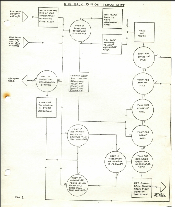
Section 1.6.2 (Cont'd) (d) If the search fails the direction of search is changed (up to six times) and the search continued. This is to avoid errors caused by the magnetic tape system misreading or failing to recognise alignment marks. The number of changes of direction allowed may be varied as experience dictates. If the programmer is uncertain of the direction in which a specified alignment mark lies, a 'Run-Back' instruction should be given, and the Master Program will change the direction of search if required. 1.6.2.2 Alignment Marks The identifier check is made on 5 numeric characters. For example, if the identifier is placed in the least significant end of the word containing the alignment mark characters, the specified identity must be quoted as : 15 15 15 15 n where n is the required identity. It is possible to use several independent sets of identifiers in the same file, the required set for any alignment being specified in the Intercode instruction by I (location of required identifier in block). In any block containing alignment mark characters, any word which is allocated to a set of identifiers MUST BE ZERO when not containing an identifier. 1.6.2.3 Alignment of Tape Following Instruction The tape is aligned at the end of the process such that an Intercode read instruction will make available to the program the block containing the specified identity, or a write instruction overwrite the following block. Intercode instructions 46, 47 may be used to change the 'function' of the file from Input to Output or vice versa except in the case of Run Forward, which may only be used when the file is currently being used for Input. 1.6.2.4 Time Taken by Alignment Instructions The time taken by the magnetic tape alignment instructions is approximately t + n seconds, where t is the time (in seconds) required to traverse the tape without stopping, and n is the number of alignment mark blocks encountered in the search. This rule is applicable to the case where changes of direction take place, provided that the values assigned to t and n are adjusted as required. The case of multi-reel alignment is not covered by the formula. Time-sharing can take place only during the t seconds of the t + n. If the 'Interruptible count 500 m.s. Routine' is incorporated in the Master Routine, time sharing can take place during the n seconds and it is also possible to have access to another tape deck on the same assembler. 6/5 Amendment No. 32 November 1966
Section 1.6.3 1.6.3 Step Specified Number of Blocks - Intercode Actions 48, 49 These instructions cause the file to be aligned forward or back a specified number of blocks, due correction being made in the case of alignment across reels of a multi-reel file. Before stepping back on an output file, a 'FINIS' block and the End of File Sentinel blocks are written. No additional information is required on the file, the block serial numbers used are automatically written by the Master Programme into the first word of every data block when the file is written. These instructions may be used to change the 'function' of the file from Input to Output or vice versa, except in the case of step forward - which may only be used when the current function is Input. The instruction 'step back zero blocks on an input file to be used for output' will be interpreted as a change of function which does not involve re-alignment of the file. In fact, a re-alignment of the tape will be required, as a promoted read instruction (of which the programmer is unaware) will have already taken place. The time for the instruction will be approximately the time taken to read the number of blocks traversed (plus one second on step back). This excludes the time taken to deal with events such as doubtful block, and assumes that it is not necessary to change reels. When alignment over multi-reel occurs, each subsequent reel in the 'step back' procedure must be aligned at the end before the alignment can continue. 1.6.4 Relative Merits of 'Step' and 'Run' The advantage of the 'step' facility over the 'run' facility is that the file does not need to be specially set up. On the other hand, the 'run' facility may often be easier to programme, particularly when it is desirable to align at the start of a batch of data consisting of a variable number of blocks. The time factors are such that running to mark traverses the tape faster than stepping forward or back, but each alignment mark not required imposes an overhead of 1 second. This overhead is equivalent to the time saved on 320 blocks (independent of block size). In other words, considering only the time factor, 'run to mark' should only be used for an alignment if the 'marked blocks' to be skipped occur on average at least 320 blocks apart. Running back beyond one reel may however be more efficient than the above rule suggests due to the fact that-subsequent reels need not be aligned at the end but can be directly searched from the start of the reel,
Section 2 2 OVERFLOW ALARM 2.1 Conditions Producing Overflow If at any time arithmetic is attempted which would produce a result too large to be held in the accumulator, an overflow alarm is given. 2.2 Procedure Following an Overflow The action is completed, the contents of the Sequence Control Register are then placed in compartment 24 of division O and the instruction in compartment 25 is obeyed. The Master Programme includes an instruction in compartment 25 which is a sequence change to a special subroutine. 2.3 Master Programme Action A report is typed on the log providing the operator with the following information: (a) The Programme Identity Number of the programme currently being obeyed. (b) Contents of registers A and B. (c) Contents of the sequence control register. The programme causing overflow is closed, enabling the operator to take a Post-Mortem and Unload, or Unload directly. The programme is closed in such a way that the operator has no means of continuing with it. Note: In the Master Program with shortened overflow routine, the contents of registers A, B, and C, are stored in location (Sp+3O), (Sp+31), and (Sp+34) respectively: and the contents of compartment 24 are stored in location (Sp+45), when Sp is the start of the program switch. (If the master does not have FCC, the program switches start in locations 420, 468, 516, 564, 612, and 660 depending on the number of program switches in the Master. The program identity is found in location (Sp+39) ). If the programme causing overflow is being run under the Programme Trials Routines of the Master Programme, the programme is not closed but continues. The same information is typed. If the Master Programme gives rise to overflow a special report is typed in the log and the post-mortem routines entered immediately. The Master Programme must be reloaded. However, if modification register 1 of modifier group O is set for the start of the programme control area the over- flow routine deals with the overflow as if programme overflow had occurred, even though overflow may have occurred within the Master Programme. Note: This facility is not available in the Utility Master Programme. 6/2 Amendment No. 29 August 1966
Section 3 3 LOCKOUT ALARM 3.1 Conditions Producing an Alarm Lockout alarm is raised in connection with the store reservation system designed to ensure that no programme, other than the routines of the Master, can interfere with another. This system is optional and is not included on all machines. A four-bit tag is associated with every word of the store. The Master Programme allocates each programme a tag number (1-8) which is placed in the tag position of words forming the programme area and in the fifth quartet of all area modifiers used by the programme. The first 200 locations of the extra chapter are used by the Master Programme and have tag 14 (see section 9). At the end of every annexe and input/output section, a special annexe limit word is placed having tag 15. Areas used by the Master Programme have tag 14. The Master Programme annexe areas are given tag 13 to prevent the Master Programme corrupting itself if the area modifier in 64 + R should be corrupted. Whenever an attempt is made to use a route reserved for one programme to pass information to, or from, an area of the store reserved for another programme, the channel is closed. This happens when the fifth quartet of the area modifier is different from the tag in the annexe or input/output section, or when an annexe limit word is encountered by an assembler. When a programme bearing a tag other than 14 (or 15) makes reference to an area of the store which does not have the same tag, a 'lockout' alarm occurs, unless the store area has tag O. 3.2 Procedure Following the Alarm The alarm halts the computer in the middle of the action, and an investigation may be carried out. If the Master Programme in use has the reduced facility, the operator should note the contents of compartment 1, sequence control register, order register, and key register. When this has been completed, a key is operated which causes a skip to the end of the action. The contents of the sequence control register are placed in compartment 16 of division O and the order in compartment 17 is obeyed. This is a sequence change to the Master Programme. 3.3 Master Programme Action EITHER: A report is typed on the log including the following information: (a) Programme Identity Number of programme currently being obeyed. (b) (Contents of compartment 16) -1. This gives the location of the instruction that caused lockout, except in the case of a sequence change instruction, when it gives the location before that addressed by the sequence change. Amendment No. 29 6/2 August 1966
Section 3.3 (Cont'd) (c) Last location at which the programme was entered from the Priority Control routine. This is provided to reduce the search for a sequence change causing lookout. (d) Contents of compartment 1. This gives the location of the last 8, 19, 20 - 22, 28 or 29 action obeyed. The programme causing lockout is closed, enabling the operator to take a Post-Mortem and Unload, or Unload directly. The programme is closed in such a way that the operator has no means of continuing with it. OR: If the Master Programme causes lockout a special report is typed in the log. The operator should load the Independent Store Print programme on the appropriate route. This programme will then be entered immediately the machine is re-started. The Master Programme must be reloaded. However, if modification register 1 of modifier group O is set for the start of the programme control area (see section 7.2) the lockout routine deals with the lockout as if programme lockout had occurred, even though lockout may have occurred within the Master Programme. (With the reduced Easter Programme facility): The contents of compartment 16 are stored in location Sp + 34, the contents of compartment 0 in Sp + 40, and the contents of Sp + 44 (last entry to master) in Sp +41; where Sp is the start of the programme switch (see Note in section 2.3), and a report is typed in the log to specify which programe caused lockout. Amendment No. 29 6/2 August 1966
Section 4 4 LOG ROUTINES These routines control all communication from the Master Programme to the operator, by producing the log and providing for the presentation of options. 4.1 The Means of Communication An electric typewriter provides the means of communication from the Master Programme to the operator. The typewriter may be linked to either the General Purpose Output Assembler (together with paper tape, punched card or printer output) or the Paper Tape Output Assembler (together with paper tape output if required). 4.2 The Presentation of Options When either a programme or a routine of the Master requires the operator to make a decision, options are offered. The Log routines allow only one request for a decision to be offered to the operator at any one time, other requests being queued. 4.2.1 Master Programme Options While a programme is running the Master Programme may require a decision by the operator. The procedure is standardised. The Log routines offer options by typing in the computer log: (a) A reference indicating that options are being offered and an alarm number specifying the cause of the alarm. (b) The identity number of the programme concerned. (c) Any further information required. Amendment No. 18 4/O January 1964
Section 4.3 The Master Program alarm numbers consist of four digits indicating: (Alarm type) (Channel) (Channel) (Route) A special warning light is lit on the operators' control desk whilst an answer to option is awaited. 4.2.2 Operational Progam Options A program may use the Intercode 'Offer Options' instruction to obtain a decision from the operator. Information is displayed and entered in the log as for Master Program options, except that no 'further information' can be given. Operational program alarm numbers consist of two digits. 4.2.3 Program Comment in Log A facility is provided to enable the program to output up to 35 characters of information on the log (see section 5, action 154, Volume III). It is essential that the information contains program identification to distinguish between comments when timesharing. 4.3 The Record of Activities In addition to details of options offered, the following forms of comment are also typed: (a) Warnings: These require operator action. (b) Comments: These are for information and do not require operator action. They provide a record for all magnetic tape usage, of the facilities used by a program and the course of any job. 4.4 Date and Time The time in minutes is given as the first two characters of every log comment. The date and time (in hours and minutes) are included in the allocation comment when any program is loaded. As an additional optional facility, the time in hours and minutes may be typed with every twentieth block comment. The date is fed to the Master Program when it is loaded and is stored in compartment 138 of division O. The time is obtained from the counter in 156 which is updated by the hardware Saxby Clock (Volume 1 Section 10.4) 6/2 Amendment No.31 October 1966
Section 5 5 OPERATOR INTERVENTION ROUTINES The 'Operator Intervention' routines control all communications from the operator to the Master Program. 5.1 The Means of Communication For all communications to the Master Program the operator stacks information into the Indicator Register, by setting a binary-decimal pattern on the indicator keys and pressing the Stack Indicators key, which places the selected pattern in the Indicator Register and sets a request for interruption. The routines first determine whether the Master Program is able to deal with the operator intervention; (an operator's choice of options (see section 5.2) will always be dealt with). If not, it arranges to type a comment the next time the typewriter is used, informing the operator that his command has been ignored. Otherwise, the routines determine whether the pattern stacked was a command (see section 5.3) and take action accordingly. 5.2 Operator Commands There are 12 indicator keys. Keys 9 - 12 are used to specify the type or 'Group' of communication; the remaining keys specify the communication within the group (referred to as the 'Function'). The groups are :- O Operator choice of options 1 Operator commands without control data (this group is optional) 2 Operator commands requiring control data 3 Store post-mortem commands (this group is optional) 4 Operator commands requiring control data 5 'Abandon Command' command 6 'Set Route Available' command 7 'Withdraw Route' command The number of the route (relative to the card/paper tape input assembler) on which control data is being submitted is given in bits 5 to 8 of the pattern stacked for appropriate commands. For those commands requiring control data a range check is made on the route number to ensure that it is a possible route for the given installation. For installations with both paper tape and punched card input, the range is O to 6; for those with only paper tape input 0 to 3, and for those with only punched card input 4 to 6. 6/3 Amendment No. 32 November 1966
Section 5.2.(Cont'd) When interruption occurs as a consequence of operator intervention the Priority Control routines (see section 6) will pass control to the Operator Intervention Routines. These use the log routines to record the nature of the intervention, and then take action according to the pattern the operator has stacked. 5.5 The Operator's Choice of Options If the pattern stacked is an operator's choice of options (Group O communication) the routines check that the choice made is in fact one of those offered. (Whenever options are offered, the set of 'legitimate' choices is specified to the Operator Intervention Routines and these routines make a check on the operators choice of options). If not, a log entry is made to this effect and the offer is still considered to stand. Otherwise the selection is noted in the log, and control is passed. to the selected part of the initiating program or routines of the Master. There is a standard list of option numbers from which the answer to any Master Program option can be selected. This of course cannot apply in the case of program options, and the significance of the option numbers from which answers may be selected must therefore be specified in the program's operating instructions. Choice of option number 10 enables the operator to defer his decision. Options are re-offered after 3 minutes. This applies to both Master Program and program options. For Master Program options only, choice of option number 1 causes the abandonment of the program on whose behalf options are being offered by the Master Program. Note : Each of these options may or may not be provided in the Master Program, according to users' requirements. A full list of Master Program options is given in Appendix B. 5.4 Acting on Operator's Commands If the pattern stacked is of group 1, 2, 3, 4, 6 or 7, the Operator Intervention Routines pass control to the particular routines concerned. The Operator Intervention Routines perform a range check on the patterns stacked for group number and function within group; they arrange to reject if the checks fail, and a report is typed in the log. All commands received are recorded in the log, except those in group 3. 6/5 Amendment No. 32 November 1966
Section 5.5 5.5 Master Routine Use of Indicators If Indicators 1-7 are set, this means that the Master Routine is in a non-interruptible mode. This occurs in such routines as an overlay and allocation. Indicator 8 is used to denote that an option is outstanding. Indicator 12 is set if a type- writer alarm occurs and Indicator 13 is used to set the machine interruptible. Amendment No. 4/41 6/8 March 1968.
Section 6 6 PRIORITY CONTROL ROUTINES 6.1 Priority Arrangement Each programme is given a 'priority class' by the programmer: Master Programme .. .. .. .. .. .. .. .. .. .. 1 'Pseudo-off-line' programmes, and programmes requiring little use of the arithmetic unit .. 2 Main programmes .. .. .. .. .. .. .. .. .. .. 3 'Fi1ler' programmes .. .. .. .. .. .. .. .. .. 4 Within classes 2, 3 and 4 priority is in order of time of loading, although the operator has the facility to re-order the list, (see section 6.3). The operator may command the Master Programme to type out the 'priority list' in the log. The priority class and identity of all programmes in the priority list are typed out (except the Master Programme). Note: Facilities to re-order and to type the list are optional in the Master Programme. The 'priority list' is amended whenever a programme is loaded or unloaded. 6.1.2 Priorities within the Master Programme The Master routines are held in the following priority order: (i) Log Routines (ii) Operator Intervention Routines (iii) Input/Output Control Routines 6.1.3 Special Operator Instruction The priority list can be amended by operator command (this is an optional facility). The positions in the priority list of the programme specified by the control data and the programme immediately above it are interchanged A comment is typed in the log giving the identity of the specified programme. If the specified programme has the highest position (excluding the Master Programme) the command is rejected and the operator informed. Amendment No. 27 6/1 February 1965
Section 6.2 6.2 Purpose of Priority Control Routines The purpose of these routines is to control timesharing by ensuring that control is always with the highest priority programe that can proceed. Control is passed to a programme of lower priority when: 1 A route required by the current programme is found to be engaged. (see section 6.3). 2 The current programme uses the Interoode 150 action and is waiting for the operator's option choice. (see section 6.4). 3 The programe is closed by operator command. This command is an optional facility. Control is passed to a programme of higher priority when: 1 A route required by the higher programme becomes available. (see section 6.5). 2 An operator's choice of options is made for it. (see section 6.5). 3 It is opened by operator command after having been closed by command. The 'Re-open Programme' command is an optional facility. Also included are facilities for timing programmes (see section 6.6), and routines to control use of the log routines (sees section 6.7). 6.3 Action when a route is found to be engaged When a programme requires to input or output information by a Group 4 Interoode Action, control is passed to the Input/Output Control Routines. These arrange to set up a 'test route' instruction in the appropriate control area. If the route is found to be engaged control is passed to the next programme in the priority queue. If the programme is of lowest priority an interruptible 'howl' is entered until any programme can continue. 6.4 Action when an operator decision is awaited When a programme has used the Interoode 150 action and is waiting for the operator's choice of options, control is passed to the next programme in the priority queue. If the programme is of the lowest priority an interruptible 'howl' is entered until any programme can continue. Amendment No. 27 6/1 February 1965
Section 6.5 6.5 Action when a route becomes available or an operator decision is made When a route which having been tested and found to be engaged becomes available, or if the operator presses the stack indicators key, or a route is set from manual to computer, a request for interruption flip-flop is set. This flip-flop is also set at intervals of one second, and is driven by the millisecond timer if this is supplied. The computer operates in two modes, the interruptible and non-interruptible as determined by computer code actions. If the request for interruption is set, interruption will occur as soon as the computer is put into the interruptible mode, if it is not already in that mode. Interruption sets the computer into the non-interruptible mode, resets all requests for interruption and places the contents of the sequence control register into compartment 8 of division O. The instruction in compartment 9 of division O is then obeyed. The instruction in compartment 9 is a sequence change into the priority control routines which store the contents of registers A, B and C in the program control area of the program just left by interruption, and store the contents of compartment 8 for return to that program. The routines then determine if the log routines have information still to be output, and arrange to enter the log routines as required. If the log is not required to be used the routines determine if interruption was caused by the operator stacking indicators as a command or as a choice of options; and if it was, enters the Operator Intervention routines (see section 5). Otherwise the routines determine if a new log entry is required and arrange to enter the log routines to initiate it. If no requests for the log are set control is passed back to the highest priority program capable of continuing. When control is passed back to the program, the required modifier group is set, registers A, B and C are restored and a sequence change made back to the program, which also sets the computer in the interruptible mode. 6.6 Timing Facilities 6.6.1 Time spent in Programs The program timing routine is an optional facility available on all installations fitted with the hardware millisecond timer. On loading the Master Program this routine is inactive; it may be turned on or off by the start and stop timing commands. In the active state the timing routine costs an overhead of 25% extra time in the priority control routine. 6/2 Amendment No. 31 October 1966
Section 6.6.1 (Cont'd) The operation of the millisecond timer is independent of the computer even when the latter is halted (e.g. by lockout). A counter is maintained in the store (division O compartment 157) which is stepped by 1 every millisecond. The timing counter is cleared when entry is made to any program. On return from the program the contents of the counter are augmented to a total in its control area which thus represents the time spent in the program. For timing purposes some common routines of the Master Program are charged to the program using them. These routines are:- 1 Input/Output Control routines excluding the time spent in dealing with route alarms and delay in obtaining access to an assembler. 2 Programmed offer of options routine up to the point where control is passed to the log routine. 3 Program comment routine. 4 Unload routine up to the point where control is vested in the master routine control area. 5 Overlay routine. Because interruption automatically occurs before the timer reaches its maximum value there is no possibility of passing through zero before augmenting the time to a programs counter. The time is output on the typewriter as part of the END and ABDON comments in minutes and seconds rounded off. 6.6.2 Ineffective time This time is obtained from a counter at the bottom of the priority queue. This counter counts the number of actions performed there between interruptions while waiting for some program to continue. It is converted into minutes and seconds by multiplying by a factor dependent on the action speeds of LEO III, 326 or 360. Each END and ABDON comment displays the ineffective time since the previous such comment. For installations which do not practise a high degree of timesharing, the efficiency when sharing an assembler between more than one program can be increased by the presence of the ineffective time routine. This effect is produced by the decrease in the ratio (time spent in priority control routine between neighbouring program control areas) to (total time spent in priority control routine). 6/2 Amendment No.31 October 1966
Section 6.6.3 (Cont'd) 6.6.3 3 Minute delay The 3 minute delay routine is used by the route closed (Section 1.2.1.1) and deferred option (Section 5.3) routines. The delay is produced by setting the associated time counter in the program control area 3 minutes ahead of present time. At each entry to the program control area a comparison is made between present and associated times until the 3 minute delay is completed. Present time is as given by the Saxby Clock (Section 4.4) on installations having this hardware facility. On other installations the clock is simulated by a counter based on the number of entries to the priority queue. 6.7 Request for Use of Log Routines When a program uses the Intercode 150 action the Priority Control routines set up a request for access to the log routines, and arrange to return to the program at the correct point once an option choice has been made. When a program uses the Intercode 154 action the Priority Control routines set up a request for access to the Log routines and arrange re-entry to the program. 6/2 Amendment No. 31 October 1966
Section 7 7 ALLOCATION AND LOADING PROCEDURES 7.1 Purpose of Allocation The computer facilities may be divided into two classes : (i) those of which common use is made by all programs running at a particular time (e.g. Arithmetic Unit) . Access to these is regulated by the Priority Control Routines (see section 6). (ii) those whose use cannot be shared (e.g. an input or output route, particular store compartments). Such facilities are allocated to programs according to their requirement by reference to a table of available facilities maintained within the Master Program. Allocation of facilities and program loading are carried out by the Program Loading Sequence which is generated by the Intercode Translator and written in front of the computer code version of every program. 7.2 Facilities Requiring Allocation These are : (a) Floating Point Only one program in the computer may use the floating point facility. (b) Modifier Groups The computer has 12 modifier registers. These are divided into four groups each of three registers. A computer code instruction can specify the required modifier register only within the current group, this being specified by bits 14 and 15 of register I, which can be changed only by the Master Program. Modifier Group 1 is reserved for the first program allocated, Group 2 is reserved for the second program. An optional facility exists whereby all other programs share Modifier Group 3, the current value being stored and restored as necessary. The Master Program also uses Modifier Group 3 for certain routines. When a program which uses Modifier Group 1 or 2 reaches End, this group is given to the next program to be allocated. One group of registers is reserved for the Master Program. 6/5 Amendment No. 32 November 1966
Section 7.3 (c) Store Every programme is divided into chapters, no chapter exceeding one division of the store (4096 words). Allocation of storage is attempted subject to the constraint that no chapter shall be broken, or lie in more than one division of the store, in order to facilitate inter-division references. No other restriction is applied, chapters may be stored in any order and may be placed between chapters of other programmes. Availability tables are maintained of the store size, peripheral equipment and other facilities. Note: On two division installations where extra economy of store space is necessary an 'overwrite allocate' facility can be provided with the Master Programme. This makes the store space occupied by the command routines available for allocation. Once the overwrite allocate command has been given, no other command except 'store dump' is available, and the Master Programme must be reloaded before attempting to allocate the next progrcnme. (d) Area Modifiers Each file has an annexe associated with it, allocated by the Master Programme. Both annexes and input/output sections specified by the programmer, must be associated with an area modifier which is used by the Interchange Area Addresses instruction (see section 1.1.2). Note: The Intercode 42 and 43 actions must always specify an input/output section in the continuation line of the action. (e) Peripheral Eguipment Programmes are allocated peripheral equipment and routes as required. The routes table is updated to remove the allocated equipment from the availability list. (f) Tags The lowest tag number available in the range 1 to 8 is allocated to each programme. 7.3 Maintenance of Records of Available Facilities The Master Programme keeps tables of available facilities which are updated after allocation to indicate facilities becoming non-available due to allocation. The record of storage is held as a table specifying in ascending order the length of strip of store available and the absolute address of the start of each strip. No strip may be longer than one division. Amendment Ho. 29 6/2 August 1966
Section 7.4 The record of peripheral equipment is held as a table specifying: route type - as on the Intercode Program Heading Sheets, associated channel, and the routes within the channel which have the specified equipment attachable. When allocation is possible the details are recorded in these tables and in the log. When allocation is not possible the fact is noted in the log but no other record kept. 7.4 Reguest for Allocation When a program is to be run, an operator command is given requesting allocation of facilities to the program. The program identity is specified on control data accompanying the command, to enable the Master Program to search for it on the magnetic tape program file. The control data also specifies whether 'normal' or 'trials' allocation is required, and, if the Multi-Route facility is chosen, the channel and route upon which the program tape is to be read. (see Appendix B.4). Before allocation is attempted the program identity is tested to ensure that a program of the same identity is not already in the computer. If there is such a program, the allocation request is rejected. Note: When an 'overwrite allocate' command has been given, the priority queue is tested to ensure that no program is in the computer. If there is such a program, the allocation request is rejected. If there is no program in the computer, the store table is set up to overwrite the command routines. If allocation is successful, the program is loaded and entered without further operator command. 7.4.1 Program Control Data (see Appendix B.4 for layout) Fifteen alpha characters can be fed on the control data for the allocate and amend run number commands. After both commands the program is entered at the initial entry point with decimal radix set, and the contents of registers A and B set as follows: (i) If the first of the fifteen characters is a block end character, (A) and (B) are left clear. (ii) If the first of the fifteen alpha characters is not a block end character, the first 5 are placed in A, and the second 5 in B. The remaining 5 characters specify the channel and route upon which the program tape is to be read. 7.5 Procedure The Master Program searches for an area of store large enough to contain the first ('Unloader') chapter of the Program Loading Sequence 6/5 Amendment No. 32 November 1966
Section 7.5 (Cont'd) (360 short compartments). This area of store can be either an unoccupied area or the special chapter of a program that has reached end. If neither of these are found a rejection report is made in the log; otherwise the Master Program 'Load Chapter' subroutine loads the 'Unloader' chapter of the P.L.S. 7.5.1 Description of the Program Loading Sequence The P.L.S. is in the form of several chapters holding allocating, loading and unloading routines. Between chapters there are data blocks used to hold the allocation requirements of the program being loaded. Subsequent chapters overlay the first and each other. The special chapter of all programs is used to hold permanent P.L.S. records and a parameter table, used to load the program. The layout of the P.L.S. on the program file is as follows: (i) Heading block (ii) 'Unloader' chapter (iii) 'Allocate storage' chapter (iv) General allocation details (v) 'Allocate routes/transit areas' chapter (vi) Route/transit area requirements (vii) 'Allocate floating point/modification group/tag' chapter (viii) 'Set up switch/construct parameter table' chapter (ix) 'Load program' chapter When the 'Unloader' chapter of the P.L.S. has been read in, if it was read into an empty area of store it sets a modification register to search the program priority list of the Master Program for a program that has reached end (or has been abandoned). If the 'Unloader' cannot find such a program the 'Allocate storage' chapter of the P.L.S. is read onto the 'Unloader', and entered. If the 'Unloader' can find such a program, or was in fact read into the special chapter of such a program initially it proceeds to unload this program. In either case, the 'Unloader' first sets a switch in the program of immediate priority to bypass this latter program in the event of the higher priority program becoming engaged. 7.5.2 Unloading a Program To unload a program, the 'Unloader' performs the following tasks: (i) If the program used floating point, clears compartments 128 to 133 of division O and sets tag 14; (ii) If the program used Modifier Group 1 or 2, the registers are set with tag 14; Amendment No.32 November 1966
Section 7.5 (Cont'd) (iii) restores the programme tag to the availability word; (iv) unloads the route/transit areas by restoring the route type to the area modifier; (v) sets the storage area with tag 14 and clears it; (vi) deletes the unloaded programme from the priority list. The 'Allocate storage" chapter is then read onto the 'Un1oader' and entered. 7.5.3 Allocating and Loading a Programme (i) 'Allocate Storage' Chapter This reads and stores the general allocation details block, containing chapter lengths in chapter number order. It examines the available storage list and by taking all combinations of the chapter lengths, chooses the combination which will leave the smallest remainder when allocated to the shortest strip. The chapters thus allocated are discarded, the remaining chapters allocated by the same method to the next shortest strip, etc. until all chapters have been allocated. Should the end of the table be reached before allocation is completed, the report 'REJECT C' is made by re-entering the Master Programme. The storage now available is sorted into order, but the Master table is not updated at this point. Where several chapters are allocated to a strip, they are placed therein in chapter number order. Chapters are aligned to the division start or end (as appropriate) but if neither the strip start nor end is a division boundary, alignment is to the strip start. This chapter will have calculated the special chapter start of the programme being allocated, and now alters certain parameters so that subsequent chapters of the P.L.S. are read into compartments 98 onwards of the allocated special chapter area. It also copies its results to compartments O to 97 of the special chapter, viz: new storage availability, general allocation details and chapter starts/end. The next chapter is read and entered. (ii) 'Allocate Routes' Chapter This sets up the complete ALLOC comment in compartments O to 79 of the programme's first chapter and sets up the P.L.S. records in the special chapter in their final form. Amendment No. 20 3/4 March 1964
Section 7.5 (Cont'd) It allocates routes and transit areas by searching compartments 64 to 127 for the earliest match with the given route type, searching 127 to 64 if reverse allocating. If there is no match with route type 7, a match is sought with route type 8 and vice versa, before abandoning allocation. Transit areas are allocated first on the pattern 0££££, then if no match, successively on route types 1, 2, 3 ... 9. An alternate route is allocated immediately after the main route, but may be on a different assembler for MT. Should no match be found the Master Program is re-entered to make the report 'REJECT D'. The next chapter is read in over the 'Allocate routes' chapter, and entered. (iii) 'Allocate Floating Point/Modification Group/Tag' Chapter This allocates floating point facilities, if required, by checking that A* has tag 14. A modification group is allocated by finding the first MR1 with tag 14, otherwise the program shares Modifier Group 3. The tag is allocated by taking the next non-zero quartet from the least significant end of the tag availability word. Failure to allocate floating point is indicated by 'REJECT A' and failure to allocate a tag by 'REJECT B@. If the installation has both high and low density magnetic tape facilities, the allocation control data contains giving the file identities of those tapes to be written in the low density mode; a match is sought with the program's file and an indicator is set corresponding to the allocated route number (while checking that the route type indicates a MT file). Failure to find a match or superfluous files on the control data is indicated by 'REJECT E'. The file details in the P.L.S. records are set up in their final form, and the next chapter is read over this one and entered. (iv) 'Set Up Switch/Construct Parameter Table' Chapter This chapter is only entered when the program is known to be allocatable and one of its tasks is to update all Master records for the new program. It also types the ALLOC comment, and clears the program's area before loading. From the allocated tag T, the program's switch start is calculated = 48 (T + 1) + contents of division O compartment 2 6/5 Amendment No.32 November 1966
Section 7.5 (Cont'd) The new programme is sorted into the priority list, and the orders in the switch of the programme of immediate priority to this one, are updated. The switch working compartments are set up, including the initial value of A, B from control data; the switch is left in the 'closed' state until the programme has been loaded into the store. The facilities tables are updated by stacking programme tag in A* and the allocated modification group, by placing the area modifier in 64 to 127, by updating the tag availability word, and by copying the new storage availability table. The programme's parameter table is constructed in 98 to 139 of the special chapter, and a DATE/TIME comment is made in the log, followed by the ALLOC comment. The final chapter is then read into compartments 140 to 199 of the special chapter. (v) 'Load Programme' Chapter This loads all the initial chapters of the programme, and then sets the annexe limit words with tag 15. The programme switch is 'opened', modification group O is set, and the Master Programme is entered with: division O compartment 26 = programme switch start division O compartment 27 = programme special chapter start Amendment Not 20 March 1964
Section 7.6 7.6 Programme Control Data Ten alpha characters can be fed to a programme on the control data for the allocation and amend run number command. After both commands the programme is entered at the initial entry point with decimal radix set and the contents of registers A and B set as follows: (i) If the first of the ten alpha characters is a block end character (A) and (B) are cleared. (ii) If the first of the ten alpha characters is not a block end character the first 5 are placed in A and the second 5 in B. Amendment No. 19 3/3 February 1964
Section 8 8 THE ABANDON ROUTINE If a programme does not reach end it must be adandoned by operator command. If, however, the programme does reach end no further operator command is required. In both cases the programme is closed down and an end indicator set for the Programme Loading System. If the programme is under trial the Programme Trials End routines are entered, but a final dump is only taken in the event of the programme not reaching end. A log entry is made. When the next allocate command is given the Programme Loading System will unload any programmes which have the end indicator set. The 5/O/1 command abandons the previous command with the appropriate comment provided that command has not been obeyed. If the previous command has been obeyed the 5/O/1 command will be rejected. 6/2 Amendment No. 29 August 1966
Section 9 9 STORE DUMP ROUTINE 9.1 Purpose and Scope This routine (an optional facility) and the Store Post-Mortem Printout Programme provide a means of printing a post-mortem of the store when the P.T.S, post-mortem facility is not available (e.g. when P.T.S. is not in use or when a job timeshared with a P.T.S, trial requires a post-mortem). The Store Dump Routine produces a store post-mortem on magnetic tape which is then printed by the Store Post-Mortem Printout Programme (Volume V, Part 3, Section 6). 9.2 Data There is no control data. 9.3 Results (i) Store Dump Tape with heading blocks the first of which contains Master Programme identity, date and time of post-mortem. Subsequent blocks give the identity of each programme in the store and the start and end points of its chapters. The contents of all store locations are held in double alpha form in blocks of 24 words. See Appendix C for layout of tape blocks, (ii) Log comments. 9.4 Procedure The Store Dump Routine has three main parts, the set-up routines, the dump routines and the end routines. Entry is made by Master Programme command. 9.4.1 Set-Up Routines The contents of certain compartments are stored in the Store Dump Transit Area (see Appendix C for details). Modification register 1 of modification group O is then set at the start of the Master Programme Switch Area and the Master Programme switch set to pass control to the bottom of the priority queue. The annexe start location for route 7 is stored, and those for the Store Dump route 7 and for Channel 7 route 6 (Area Modifier) are set up. If the P.T.S. is in the store, the block serial number for route 7 is stored and the P.T.S. tape is closed for input. The Store Dump Tape is opened and the Dump Routines entered. Amendment No, 27 6/1 February 1965
Section 9.5 9.4.2 Dump Routines The preserved locations stored in the Store Dump Transit Area are written as the first block. Heading blocks are then set up and written, including Master Program and commercial program identities (see Appendix C). The last program block is followed by one with program identity 15 15 15 15 15. The main loop writes blocks of 24 data words. Each long word in the store is picked up, converted to double alpha form and written on the Dump Tape. A word is preceded by a special identifier if its tag number differs from that of the previous word. 9.4.3 End Routines Entry to the End Routines is made when the store dump is completed. The Store Dump Tape is closed and unloaded, and the 'end' comment typed. If the P.T.S. routines are in store, the P.T.S. annexe start location for route 7 is restored, and if a trial is in progress the P.T.S. tape is opened for input and realigned. The normal end of command procedure is then entered. 9.5 Operating Notes 9.5.1 Facilities Required Store Dump Route 7 of magnetic tape channel on which allocation is performed. Note 1: A pool of released tapes must always be held in the Released Tapes Index. Note 2: If the required route is being used as a program tape, the tape in question should be unloaded. After the store dump has finished, this tape should be reloaded. 9.5.2 Entry to the Routine By Master Program command GROUP 3 FUNCTION 1 The P.T.S. dumps tape (if any) is unloaded. 9.5.3 Log Comments RC (Ch.Ch. 7) Store Dump tape not loaded (3-minute intervals) LOP (Ch.Ch. 7) or Store Dump tape opened HOP (Ch.Ch. 7) DUMP END Post-Mortem completed and Store Dump tape unloaded RC (Ch.Ch. 7) (following DUMP END P.T.S. tape required (3-minute intervals.) 6/7 Amendment No. 35 April 1967
Section 10 10 On-Line Store Post Mortem 10.1 Purpose and Scope This routine (an optional facility) will print out the whole store including its own area or a specified part of the store in the layout given in Appendix D. This routine is permanently in store and takes up five hundred locations at the beginning of division one. 10.2 Data There is no control data. 10.3 Results This routine will print out the program whose tag is specified (see 10.5.3.2) together with all compartments of tag 13, 14 or 15. Zero compartments are not printed except where a tag change occurs. 10.4 Procedure This routine is entered by "stacking and executing" a sequence change as specified in (10.5.3.1(3)). The data in compartment 153 of division O is used to determine the route on which to print, whether a matrix is required, and the size of the store. At the conclusion of the post-mortem or if the post-mortem has been abandoned, the master is re-entered through the priority queue. All programs will then continue normally, including those that have been printed out. 10.5 Operating Notes 10.5.1 Store Space Required Division 1: compartment O-500 10.5.2 Route Reguired Printer 10.5.3 Operating Procedure 10.5.3.1 Initiation 1 Halt 2 Check contents of compartment 153 (see Vol. V. Section 7, Appendix B) 3 "Stack and execute" a 26/O/3 order to address 178 (II:2) in division O. 4 Single step. If interruption occurs, repeat 3, otherwise restart. 6/7 Amendment No. 35 April 1967
Section 10.5.3.2 10.5.3.2 Indicator Settings To Print Whole Store No indicators set. To Print a Program The tag of the required program should be stacked on I9-11. This will print out all the program plus all the master together with all compartments of tag 13,14,15. To Restrict Print of Master If I6 is stacked at any time while the master is being printed out, the master will not be printed after the end of the last program switch. Note: This must not be stacked after finishing printing the master. To Abandon Print Stack I2 Notes: (i) After stacking a program tag on I9-11, it is not possible to revert to printing the whole store. (ii) It is possible to change the tag of the program being printed out at any time. 6/7 Amendment No 35 April 1967
Section 11. 11 Uptime Card Routines The Master Program will handle one or two uptime card readers. (i) Open File: The start of the program switch and the uptime route for the file are stored away. The counter of the number of uptime programs in store is updated. (ii) Close File: The details that were stored when the file was opened are cleared. The counter for the number of uptime programs in store is updated. (iii) Allocation and Overlay: Before the Master Program enters either the allocation or overlay routines, there is a delay if an uptime card program is in store. The purpose of this delay is to prevent the spurious rejection of cards. In allocating, these would amount to three to five cards per program on a string. During this delay, the uptime card routes are closed, except when an uptime card program is overlaying, in which case that program's route is left open. In the delay, only uptime card programs are permitted to continue, this is to enable them to pocket-select the card which is in transit. At the end of the delay, the uptime card programs are closed. They are reopened after either the overlay or allocation is finished. Also during the delay, comments are paused and commands and options are ignored. These last two measures prevent programs being lost in the priority control. The uptime card reader should be re-opened after the overlay or allocation is finished. Amendment No. 4/41 6/8 March 1968.
Appendix A APPENDIX A : EQUIPMENT AND STORE SPACE REQUIRED BY THE MASTER PROGRAMME Due to the different combinations of peripheral equipment there are slightly different versions of the Master Program for each machine. The maximum store space required by Issue 6 Master Program is 8192 short compartments and the minimum 4740 short compartments. (4540 short compartments with overwrite allocate). The two basic versions are as follows : Version A - has the routines for paper tape input, punched card input and output, General Purpose printer and magnetic tape. The typewriter and paper tape punch routines assume that output is via the General Purpose Output assembler and the Programme Trials System uses a General Purpose printer. Version B - has the routines for paper tape input, punched card input and output, special printer, and magnetic tape. The typewriter and paper tape punch routines assume that output is via the paper tape output assembler and the Programme Trials System uses a Special printer. A version for a particular installation is made by deletions from one of these basic versions. Peripherals Item When Required Purpose Typewriter Permanently (i) Communication with Operator (ii) Computer Log Card Reader or For all operator commands To read control data Paper Tape Reader of groups 2 and 4 specifying programme to which command relates Card Punch When any reel of magnetic Produces control cards for (optional) tape is loaded for output clerical control on magnetic tape Magnetic Tape Route When allocating and - loading Clock (optional) Permanently when installed To note time against log entries Millisecond Timer Permanently when installed Used for timing programmes (optional) Amendment No. 29 6/2 August 1966 |
Appendix B APPENDIX B : MASTER PROGRAMME OPERATING INSTRUCTIONS CONTENTS B.1 GENERAL NOTES B.2 GENERAL OPERATING PROCEDURE B.3 MASTER PROGRAMME COMMANDS AND LOG ENTRIES B.4 CONTROL DATA FOR OPERATOR COMMANDS B.5 MAGNETIC TAPE SENTINEL BLOCKS Amendment No. 27 6/1 February 1965
Appendix B.1 B.1 GENERAL NOTES This appendix outlines the operating procedures to be followed when LEO III/326 programmes are run under Master Programme Control. Facilities that may or may not be included in the Lester Programme, according to users' requirements and available store space, are noted in the text as 'optional facilities'. Procedures for loading and amending the Easter Programme itself are contained in Part 3 of this volume under the section heading MASTER PROGRAMME INPUT SEQUENCES. Facilities are noted as optional where appropriate in this appendix. The fully reduced Master Programme, which is produced by the omission of all optional facilities when the Master is generated, provides the following facilities: Control of timesharing (one program only) Log routine Operator Intervention: Decode indicators Deal with answers to options Commands: Group 2 - Abandon programme Group 4 - Set up Released Tapes Index for 24 tapes Allocation (without alternate routes) Read control date for commends Single annexe working for loading programmes Programme facilities : Programme Unload Programme Options Programme Output on Log Overlay Input/Output Control Open and Close Files Read/Write Set Reel Counter Rewind Run Forward and Back Step Back Amendment No. 29 6/2 August 1966
THERE IS AT LEAST ONE PAGE MISSING HERE
Appendix B.2 (Cont'd) STEP 2 Check that Green 'READY for COMMAND' lamp is lit STEP 3 Set up required pattern on Indicator Stacking Keys STEP 4 Press Stack Indicators Button STEP 5 Watch log for confirmation that command has been accepted and obeyed STEP 6 Unload control data, restore to file B.2.4 Unacceptable Commands Confirmation that the command has been accepted is indicated by the appropriate log comment (see B.3). If this is not given, the procedure should be as follows. B.2.4.1 No Log Entry is Made Reasons: 1. Checks detailed in 2.3 were not carried out OR 2. I13 is not set OR 3. Interruption has failed OR 4. Stack Indicators Button failed to operate OR 5. Master Programe corruption or computer fault Action STEP 1 Repeat command procedure with special emphasis on checks STEP 2 (If still no Log Entry) Check condition of I13 If not set, report to Engineers, suspect } failure to set I13 } If no fault found take } post—mortem of Master If set, report to Engineers suspect } Programme failure of Stack Indicators Button or of } Interrupt } Amendment No. 27 6/1 February 1965
Appendix B.2 (Cont'd) B.2.5 Unidentified Halts, etc. STEP 1 Note Contents of: Sequence Control Register Order Register Tag Register Compartment 1 if LEO 3, compartment 32 if LEO 360, 326 STEP 2 (LOCKOUT ONLY) Restart - details are typed in log. (Others) Suggested Action: Stack and execute sequence change to compartment with incompatible tag, so that 'lockout' alarm is generated. Then proceed as above. STEP 3 Enter Store Dump Routine Amendment No. 29 6/2 August 1966
Appendix B.3 ALLOCATION B.3 MASTER PROGRAMME COMMAND AND LOG ENTRIES Note: Procedures are laid out in the following pages in this order: (1) Allocation Commands and associated Log Entries (2) Other Commands and associated Log Entries (3) Other Log Entries, in alphabetical order B.3.1 Allocation Commands and Associated Log Entries B.3.1.1 Commands The command given depends on: (a) Whether normal or reverse route allocation is required (b) Whether alternate routes are to be used The appropriate command for the different cases can be found by reference to the table below. The command is given in the form of the three quartet settings. | NORMAL ALLOCATION | REVERSE ROUTE ALLOCATION | OVERWRITE ALLOCATE | | WITHOUT ALTERNATE ROUTES | 4 2 | 4 4 | 4 9 | | WITH ALTERNATE ROUTES | 2 2 | 2 4 | - | Note: After an overwrite allocate command, no other command is acceptable except store dump; Option 1 is not available. 6/2 Amendment No. 29 August 1966.
Appendix B.3 ALLOCATION B.3.1.2 The Log Entry |DATE (Date) AT (Time)| |ALLOC (Prog. No.) (Serial No.) (Run & Rerun No.) (Tag) (Modification Group No.) (Allocation Type)| 1st LINE | (Chapter Start Locations) | 2nd LINE | (File Identity) (Channel, Route) (N) | 3rd LINE Notes: (1) The Allocation Type entry may be any selection of the letters T,N, and R ( in that order if more than one present), signifying respectively: Trials allocation, No alternate routes, and Reversed route allocation. (2) On line 3; the entries are repeated for each file. (3) N in line 3 is printed when no alternate route is allocated for the file. If an alternate route is allocated, the alternate channel and route numbers are also typed on the 3rd line. 6/6 Amendment No. 34 March 1967
Appendix B.3 ALLOCATION REJECTIONS B.3.1.3 Allocation Rejections | LOG ENTRY | SIGNIFYING | |COL. 1 |COL .2 |COL.3 |COL.4 | | |C REJ A |(Prog. |(Last Prog. |GP 2 FN 2 |After the specified command with control data relating to programme in Column 2 | | | Expected) |found on | OR OR |programme was not found on the programme file on route O. | | | |file) | 4 4 | | | | | | OR | | | | | | 9 | | |C REJ B |(Prog. |GP 2 FN 2 | |The specified programme cannot be allocated as it is already in store. | | | No.) | OR OR | | | | | | 4 4 | | | | | | OR | | | | | | 9 | | | |C REJ C |(Prog. |GP 2 FN 2 | |The specified programme cannot be allocated for trial as a trial is already in progress. | | | No.) | OR OR | | | | | | 4 4 | | | |C REJ D |(Prog. |GP 2 FN 2 | |The specified programme cannot be allocated since the tape does not contain index blocks.| | | No.) | OR OR | | | | | | 4 4 | | | |C REJ E |(Prog. |GP 2 FN 2 | |The specified programme cannot be allocated as there is no room in store for the first | | | No.) | OR OR | |chapter of P.L.S. | | | | 4 4 | | | |C REJ F |(Prog. |GP 2 FN 2 | |Allocation of programme was abandoned after OPT. 1 was taken (on magnetic tape) or 5/0/1 | | | No.) | OR OR | |command. | | | | 4 4 | | | 6/2 Amendment No. 29 August 1966.
Appendix B.3 ALLOCATION REJECTIONS | LOG ENTRY | SIGNIFYING | |COL. 1 |COL .2 |COL.3 |COL.4 | | |REJECT A |(Prog. No.)| | |Modification group or Floating Point facilities requested but not available. | |REJECT B |(Prog. No.)| | |No tag or no programme control area available. | |REJECT C |(Prog. No.)| | |Insufficient store area available. | |REJECT D |(Prog. No.)| | |Not enough routes or area modifiers available. | |REJECT E |(Prog. No.)| | |A file other than one of this programme's files has been specified in the control | | | |data to be written in low density mode. (High density installations only). | |REJECT F |(Prog. No.)| | |Allocation of specified programme has been abandoned as OPT. 1 was taken for an | | | |alarm whilst programme tape was being read, or 5/O/1 command. | |REJECT G |(Prog. No.)| | |Master and PLS incompatible (i.e. Issue 3 or earlier Master, PLS by Issue 7 Translator).| Note: For all REJECT comments: all programmes awaiting unloading have been unloaded. Amendment No. 27 6/1 February 1965
OTHER COMMANDS Appendix B.3 B.3.2 Other Commands and Associated Log Entries | FACILITY COMMAND LOG ENTRY | | |Group Function | | | |I12-9|I8-5|I4-1| | + |Start Timing Programs | 1 | 0 | 1| TIMING | + |Stop Timing Programs | 1 | 0 | 2| TIMEND* | + |Print Priority List | 1 | 0 | 3| P.Q. Priority Class Program No. | | | | | | or | | | | | | P.Q. Tag. Program No. (if this is selected as an optional facility)| + |Set preferred route type | 1 | x | 4| PTAPE (or PCARD) x = 0 means P/T required | | | | | | x = 1 means card required | + |Omit Categories of Typing DB | 1 | 1 | 5| OMIT DB (or SET DB) | | Comments | | | | | |Replace categories of Typing | | | | | | SER Comments | 1 | 2 | 5| OMIT SER (or SET SER) | | Spaces | 1 | 3 | 5| OMIT SP (or SET SP) | |Note 1 EDG Comments | 1 | 4 | 5| OMIT EDG (or SET EDG) | |Unload Program Tape | 1 | 0 | 6| TAPE UNLOADED | |Rewind Program Tape | 1 | 1 | 6| TAPE REWOUND | |Print Route Availability | 1 | 0 | 7| CH(cc) RO(X0) R1(X1.......R7(X7). Where Xn is the route type if | | | | | | the route is available. P (route type) if Potentially Available | | | | | | and U if unavailable. | @ |Unallocated Store | | | | STORE A1 A2 A3 A4 A5 | |(on 1 store machines only 5 largest| | | | B1 B2 B3 B4 B5 | | strips)| 1 | 0 | 8| | | | | | | where An = nth largest strip in first store | | | | | | Bn = nth largest strip in second store | |Set Check Field on Card Input | | | | | |C=O for columns 1-1O, C=1 for | 1 | 0 | 9| CARD CHECK | |columns 6-15, etc. to C=14 for | | | | | |columns 71-80. | | | | | |Change Channel | 1 | 0 | 10| | + |Set Preferred Printer Type | 1 | 0 | 11| PREFER G.P. (or PREFER S.P.) | |Abandon Program which has not | | | | | |reached end | 2 | r | 1| ABDON (Prog. No.) (Prog. Run Time*) INEFF (mins.sec) | |Raise Prog. one posn in Priority | | | | | | Queue | 2 | r | 6| PR. CH (Prog. No.) | @ These commands only list the current situation. They do not allow for programs which have ended or been abandoned. Amendment No 4/43 December 1968.
APPENDIX B.3 OTHER COMMANDS (Cont'd) B.3.2 Other Commands and Associated Log Entries. | FACILITY COMMAND LOG ENTRY | | |Group Function | | | |I12-9|I8-5|I4-1| | |Open Prog. which has been closed | | | | | |by Command | 2 | r | 7 | RE-OPEN (Prog. No.) | |Amend Run No. (to that in Control | | | | | | Data) | 2 | r | 8 | RUNCH (Prog. No.) (New Run No.) | |Close Program | 2 | r | 9 | PAUSE (Prog. No.) | |Abandon Prog. of Tag T | 2 | T | 1O| ABDON (Prog. No.) | |Raise Prog. if Tag T one Posn in PQ| 2 | T | 11| PR. CH (Tag) | |Open Prog. of Tag T | 2 | T | 12| RE-OPEN (Tag) | |Suspend Prog. of Tag T | 2 | T | 13| PAUSE (Tag ) | + |Enter Store Dump | 3 | 0 | 1| DUMP END when Dump is finished | |Set Released Tapes Index | 4 | r | 1| RTI (Serial No. +) | + |Set Route Available | 4 | r | 6| AVAIL (Ch.Ch.Rte) | + |Set Route Not Available | 4 | r | 7| WDRAW (Ch.Ch.Rte) | + |Change Route No. | 4 | r | 8| ROUCH (New Ch.Ch.Rte.) (Old Ch.Ch.Rte.) | + |Cancel Command | 5 | 0 | 1| Same as if option 1 were taken | + |Set Route Available. Note 2. | 6 | C | r| AVAIL (Ch.Ch.Rte) | + |Set Route Not Available. Note 2. | 7 | C | r| WDRAW (Ch.Ch.Rte) | 1 If these commands are repeated, the second command will reverse the first e.g. 1/2/5 will cause resumption of SER comments. 2 In the case of Fast Channel, C = Channel No. - 8 + These are optional facilities. * Only if command 1/0/1 has been given 6/6 Amendment No. 34 March 1967.
Appendix B.3 OTHER LOG ENTRIES B.3.3 Log Entries (for forming records of commands obeyed) | LOG ENTRY | | | |COL. 1 |COL. 2 |COL. 3 |COL. 4 |COL. 5 | SIGNIFYING | ACTION | *|ABANDON |(Prog. No.)| | | |The current post-mortem point cannot |Unload program. | | | | | | |be matched in the P.T.S. Records. | | *|C IGN | | | | |A command has been ignored (given when |Normal action must be taken on | | | | | | |'Ready for Command' light not on). |the other log entry and the command| | | | | | |Note: This entry is made when next |should then be repeated. | | | | | | | entry to log is ready. | | *|CHD (Ch. |(Prog. No.)|(Block No.)|SER | |Serial number failure has occurred |The tape must be reloaded on | |Ch. r) | | | | |when expecting the specified block and |another deck and then set to the | | | | | | |the Master Program was unable to cure |route specified. | | | | | | |it at this attempt. The specified route | | | | | | | |has been unloaded ready for reloading | | | | | | | |on another deck when the Master Program | | | | | | | |will search for the required block again | | |C REJ | |GP(x) FN(y)| | |Command not recognised. |Give correct command. | |C REJ A |(Prog. No.)|GP 2FN 1 | | |Program specified in control data for |Inspect control data compare | | | | OR | | |the command in column 3 not found in |with log entry | | | | 6 | | |store. | | | | | OR | | | |1. If program number is the | | | | 7 | | | | same report to Engineers. | | | | OR | | | | Change readers, repeat command.| | | | 8 | | | |2. If program number is different | | | | OR | | | | obtain and load correct control | | | | 9 | | | | data and repeat command. | | |(Ch. Rte) |GP 4 FN 6 | | |Route specified in control data is | | | | | OR 7 | | |non-existent. | | * Entries are in Red 6/1 Amendment No. 27 February 1965
Appendix B.3 OTHER LOG ENTRIES | LOG ENTRY | | | |COL. 1 |COL. 2 |COL. 3 |COL. 4 |COL. 5 | SIGNIFYING | ACTION | | | |OR | | | | | | | | 4 8 | | |'Old' route specified in control data, | | | | | | | |is not in use by a user program, or is | | | | | | | |a paper tape input or magnetic tape file.| | |C REJ B |(Prog. No.)|GP 2 FN 6 | | |Program specified is at top of P.Q. |If C.D. is as intended, there has | | | |GP 2 FN 7 | | |Program specified to be opened has |been an attempt at duplication. | | | | | | |not been closed. |If C.D. is not as intended, obtain| | | |GP 2 FN 8 | | |An amend run number command has been |and load correct C.D. and repeat | | | | | | |given for a program which has not |command. | | | | | | |reached end. | | | |(Ch. Rte) |GP 4 FN 6 | | |Route specified to be made available | | | | | | | |already allocated or unable to be set | | | | | | | |available. | | | | | | | | | | | | | | | |Note: When a program ends, its routes | | | | | | | | remain available until the next | | | | | | | | allocate command is given. | | | | |GP 4 FN 7 | | |Route to be made unavailable already | | | | | | | |unavailable. | | | | |GP 4 FN 8 | | |'New' route, specified in control | | | | | | | |data, is either not available or of | | | | | | | |the wrong route type. | | |C REJ C |(Prog. no.)|GP 2 FN 8 | | |Program specified was a trial under | | | | | | | |P.T.S. | | 6/1 Amendment No. 27 February 1965.
Appendix B.3 OTHER LOG ENTRIES | LOG ENTRY | | | |COL. 1 |COL. 2 |COL. 3 |COL. 4 |COL. 5 | SIGNIFYING | ACTION | |DB or |(Prog. No.)|(Block |I/P | | Doubtful block on magnetic tape has | | | or | |Serial No.)|OR (No, of | |been successfully dealt with after the | | |DB 1r | | |O/P tries) | |specified number of tries. | | *|DB (Ch. |(Prog. No.)| | | |Doubtful block on channel (Cn.Ch) last |A. If PRINTER route | |Ch. r) | | | | |output was on specified route, which | 1. Mark last line | | | | | | |has been closed and is being tested. | printed as 'DOUBTFUL'| | | | | | | | 2. Align stationery to | | | | | | | | receive this line. | | | | | | | | again. | | | | | | | | 3. Open route. (Output | | | | | | | | of the block will be | | | | | | | | repeated) | | | | | | | | | | | | | | | |B. If P.T. O/P route: | | | | | | | | 1. Run out Paper Tape. | | | | | | | | 2. Mark tape for off- | | | | | | | | line removal of | | | | | | | | doubtful block. | | | | | | | | 3. Open route. (A | | | | | | | | doubtful block | | | | | | | | marker is punched). | | | | | | | | and the doubtful | | | | | | | | block repunched). | | | | | | | | | | | | | | | |C. If CARD O/P route: | | | | | | | | 1. Remove doubtful card | | | | | | | | 2. Open route. | * Entry in Red 6/1 Amendment No. 27 February 1965 |
Appendix B.3 OTHER LOG ENTRIES | LOG ENTRY | | | |COL. 1 |COL. 2 |COL. 3 |COL. 4 |COL. 5 | SIGNIFYING | ACTION | |DB 3 (r) |(Prog. No.)|(1st word |(2nd word | | A. If P.T route |1. Align on preceding block.| | | |of block) |of block) | | Following option 8, a dummy read | | | | | | | | order was given. The next block |2. Open route. | | | | | | | was then read in. | | | | | | | | | | | | | | | | Either: a doubtful block | | | | | | | | condition arose. | | | | | | | | | | | | | | | | or: the first two words of | | | | | | | | the block read were not | | | | | | | | as expected (and are | | | | | | | | here typed). | | | | | | | | | | | | | | | |B. If CARD route: |1. Align on specified card. | | | | | | | Following option 8, a doubtful | | | | | | | | block arose, or first two words |2. Open route. A block is | | | | | | | of card read were not as expected | read and a check carried | | | | | | | (and are here printed). | out as for option 8; if | | | | | | | | successful the next block| | | | | | | | is passed to the program.| |DB (Ch. |(Prog. No.)| | | |Doubtful block occurred on route |No action required as program| |Ch. r) | | | | |specified. |is using doubtful block link.| |DUMP | | | | |A Master Program dump onto magnetic | | |ABANDONED | | | | |tape has been abandoned by option 1 or | | | | | | | |5/O/1 command. | | |DUMP END | | | | |The Master Program has dumped the store| | | | | | | |onto magnetic tape. | | *|EDG (Ch. |(Prog. No.)|(Serial No.| | |No end of file sentinel found when | | |Ch. r) | |of block | | |close file instruction obeyed. | | | | |read if MT)| | |Note: This comment may occur spuriously| | | | | | | |if the end of file sentinel was origin-| | | | | | | |ally written doubtfully. | | * Entry in Red 6/8 Amendment No. 4/41 March 1968
Appendix B.3 OTHER LOG ENTRIES | LOG ENTRY | | | |COL. 1 |COL. 2 |COL. 3 |COL. 4 |COL. 5 |COL. 6 | SIGNIFYING | ACTION | |END |(Prog.No.) |(Prog.Run |INEFF | | |The specified programme has finished | | | | |Time) + |mins. | | |and will be unloaded when the next | | | | |or NT |secs.) | | |allocate command given | | |HIP (Ch. |(Prog.No.) |(Run and |(M.T. |(File Id/ | |Specified high density M.T. has been | | |Ch. r) | |Rerun No.) |Serial No.)|Reel No. | |opened for input. Source details as | | | | | | | | |specified. | | |HOP (Ch. |(Prog.No) |(Run and |(M.T. |(File Id/ |(Serial no.)|Specified high density M.T. has been | | |Ch. r) | |Rerun No.) |Serial No.)|Reel No. |optional |opened for output. Source details as | | | | | | | |facility |specified. | | *| HDG (Ch. |(Prog.No) |(File | | | |An open file check has failed Route |1. Check block read against | |Ch. r) | |Letter) | | | |has been closed and is being tested. | allocation details. | | | | | | | | |2. If details do not agree, refer | | | | | | | | | to off-line. If details do | | | | | | | | | agree, refeed; if alarm | | | | | | | | | recurs, report to Engineers. | | | | | | | | | If no fault found, take post- | | | | | | | | | mortem and abandon Master | | | | | | | | | Programme. | *| HDG (Ch. |(Prog.No) |D.B. | | | |Doubtful block occurred on open file |Check tape or card and re-align. | | Ch. r) | | | | | |or reel on specified PT or Card input |When the route has been re-opened | | | | | | | |route, which has been closed. |the block will be tested again. | *| HDG (Ch. |(Source |(Prog.No. |(Run No. |(File Id./| |An open file or reel check on magnetic|1. Check M.T. records against | | Ch. r) |Prog.No. |Required |Required |Reel No. | |tape has failed. The route has been | allocation details. | | | | | |Required) | |unloaded and is being tested | | | | |(Prog.No. |(Run No. |File Id./ | | |2. If details agree, refer to | | | |on tape |on tape |Reel No. | | | Magnetic Tape Librarian for | | | | | |on tape | | | Investigation. If details do | | | | | | | | | not agree, obtain and load | | | | | | | | | expected file on specified route.| * Entry in Red 6/2 Amendment No. 29 August 1966. |
Appendix B.3 OTHER LOG ENTRIES | LOG ENTRY | | | |COL. 1 |COL. 2 |COL. 3 |COL. 4 |COL. 5 |COL. 6 | SIGNIFYING | ACTION | |HDG (Ch. |(Source |HIGH | - | - | - |The specified low density deck |Either: | |Ch. r) |Prog.No. | | | | |has a tape loaded on it written |Rerun program on a high density | | | | | | | |in high density. |machine | | | | | | | | |or: | | | | | | | | |Copy the tape to low density on a | | | | | | | | |high density machine. | |LET |(Ch.Ch.r) |(Prog.No. | | | |The specified programme has released | | | | | | | | |the specified route using the Inter- | | | | | | | | |code 156 action. | | |LIP (Ch. |(Prog.No.) |(Run and |(M.T. |(File Id/ | |Specified low density magnetic tape | | |Ch. r) | |Rerun No.) |Serial No.)|Reel No. | |has been opened for input. Source | | | | | | | | |details as specified. | | |LOP (Ch. |(Prog.No) |(Run and |(M.T. |(File Id/ |(Serial no.)|Specified low density magnetic tape | | |Ch. r) | |Rerun No.) |Serial No.)|Reel No. |optional |has been opened for output for the | | | | | | | |facility |first time. | | * |L'OUT |(Prog.No. |(Contents |(Last |Contents | |LOCKOUT occurred; details as typed |Post-mortem and abandon programme. | | | |of [compt. |Entry |of (compt.| | | | | | |16]-1) |Point) |1*)-1 | | | | | | | | |*(compt32)| | | | | | | | |if a fast | | | | | | | | |machine | | | | * |L'OUT |(Prog.No. | | | | |LOCKOUT occurred in the specified |Post-mortem and abandon programme. | # | | | | | | |programme | | * |NEW 3(rte)|(Prog.No ) |(File Id/ |Source | | |END OF REEL sentinel found or | 1. Load specified reel on | | | |Reel No. |Prog.No. | | |written; route has been closed or | specified route. | * |NEW (Ch. |(Prog.No. |(Reel No. | | | |unloaded and is being tested. | | |Ch. r) | |Required | | | | | 2. Open route. | # This comment is an alternative to the previous one. * Entry in red. 6/2 Amendment No. 29 August 1966.
Appendix B.3 OTHER LOG ENTRIES | LOG ENTRY | | | |COL. 1 |COL. 2 |COL. 3 |COL. 4 |COL. 5 |COL. 6 | SIGNIFYING | ACTION | * |NO CD |A | | | | |Either: (a) programme identity |CHECK DATA | | | | | | | | specified as zero. | | | | | | | | |or: (b) an R.T.I command has |If correct, refeed and repeat | | | | | | | | been given and the |command. If alarm recurs, switch | | | | | | | | second control data |readers and repeat command. If | | | | | | | | word is non-zero |alarm recurs, post-mortem and | | | | | | | | |reload Master. | | | | | | | | | | | | | | | | |In either case the command is | | | | | | | | |ignored. | | * Entry in Red 6/2 Amendment No. 29 August 1966.
Appendix B.3 OTHER LOG ENTRIES | LOG ENTRY | | | |COL. 1 |COL. 2 |COL. 3 |COL. 4 |COL. 5 | SIGNIFYING | ACTION | | |B | | | |First word not control data word. |If incorrect, obtain correct | | | | | | |Command is ignored |data and repeat command. | | |C | | | |The specified route for the control | | | | | | | |data 1s not available on this machine.| | | |D | | | |Option has been taken for alarm | | | | | | | |whilst reading control data. | | * |OFLOW |(Prog No.) |(Contents |(Contents |(24)-1 |Overflow occurred in specified |Post-mortem and abandon | | | |Reg. A) |Reg. B) | |program, the contents of A and B |program. | | | | | | |being as typed. Column 5 gives the | | | | | | | |address of the instruction that | | | | | | | |caused overflow. The program has been| | | | | | | |closed. | | * |OFLOW |(Prog No.) | | | |Overflow occurred in specified |Post-mortem and abandon | + | | | | | |program, which has been closed. |program. | |O'LAY |(Prog.No. | | | |The specified program has | | | | | | | |commenced overlaying | | + This comment is an alternative to the previous one. * Entry in Red. 6/1 Amendment No. 27 February. 1965.
Appendix B.3 OTHER LOG ENTRIES | LOG ENTRY | | | |COL. 1 |COL. 2 |COL. 3 |COL. 4 |COL. 5 | SIGNIFYING | ACTION | * |O REJ |(Opt. No.) | | | |Option taken, as specified, is not |1. If specified option does not | | | | | | |acceptab1e. Master Programme awaits | correspond to that intended, | | | | | | |an acceptable option. | repeat with correct one. | | | | | | | | | | | | | | | |2. If specified option is as | | | | | | | | intended, refer to operating | | | | | | | | instructions. If option is | | | | | | | | listed as acceptable: | | | | | | | | | | | | | | | | A. If Master Programme offer | | | | | | | | of options, take an | | | | | | | | independent store post- | | | | | | | | mortem and then refeed | | | | | | | | the Master Programme. | | | | | | | | | | | | | | | | B. If programme offer of | | | | | | | | options take programme | | | | | | | | ABANDON option if | | | | | | | | available; if not OPT.10; | | | | | | | | close programme, post- | | | | | | | | mortem and abandon. | * |RC (Ch. |(Prog. No. | | | |Specified route has been found |1. Check for channel condition; | |Ch. r) | | | | |closed. Route continues to be | take appropriate action. | | | | | | |tested. | | | | | | | | |2. Check route and equipment | | | | | | | | conditions. | | | | | | | | | | | | | | | | (Note: is any equipment | | | | | | | | switched to this route?) | | | | | | | | | | | | | | | | If no apparent reason for | | | | | | | | warning, report to Engineers. | | | | | | | | If route is not opened, entry | | | | | | | | is repeated every 3 minutes; | * Entry in Red 6/1 Amendment No. 27 February 1965
Appendix B.3 OTHER LOG ENTRIES | LOG ENTRY | | | |COL. 1 |COL. 2 |COL. 3 |COL. 4 |COL. 5 | SIGNIFYING | ACTION | |R.T.I. | | | | |A list of released tapes has been | | | | | | | |fed to the Master Program | | |RTI Ch. |(Prog.No. |(Found M.T.| | |Magnetic tape loaded on route |If tape loaded is in | |Ch. R | |Serial No.)| | |specified (and allocated for |accordance with loading | | | | | | |output) is not on released |list: | | | | | | |tapes index | | | | | | | | |Either: Load a tape listed | | | | | | | |in RTI | | | | | | | | | | | | | | | |OR: Refer to Magnetic | | | | | | | | Tape Librarian | | | | | | | | and Off-Line | | | | | | | | Controller | | | | | | | | | | | | | | | |If tape is not specified | | | | | | | |in loading list, locate | | | | | | | |and load the specified | | | | | | | |tape. | t |SER (Ch. |(Prog.No.) |(Block y) |(Block x) | |The Master Program found block | | |Ch. r) | | | | |x, but successfully found block | | | | | | | |y after searching for it | | * |SNT 03(r) |(Prog.No) | | | |An unexpected (start of reel or |1. Check block | | | | | | |end of file) sentinel has been | | | | | | | |recognised on specified route, |2. Feed next block | | | | | | |which has been closed and is | required by program. | | | | | | |being tested | (If block is accept- | | | | | | | | able, program | | | | | | | | continues) | | | | | | | | | | | | | | | |3. If block is refused, | | | | | | | | take post-mortem and | | | | | | | | abandon Master Program | 6/7 Amendment No. 35 April 1967
Appendix B.3 OTHER LOG ENTRIES | LOG ENTRY | | | |COL. 1 |COL. 2 |COL. 3 |COL. 4 |COL. 5 | SIGNIFYING | ACTION | |TROFL |(Prog.No. |(Contents |(Contents |[(24)-1] |Overflow has occurred in the | | | | |Reg. A) |Reg. B) | |program under trial. The | | | | | | | |program continues | | |UA |(Prog.No. |(Absolute | | |Program has tried to obey |Store dump for specified | | | |location | | |an unassigned action (fast |program | | | |of action) | | |machine only) | | 6/7 Amendment No. 35 April 1967
Appendix B.3 OTHER LOG ENTRIES | LOG ENTRY | | | |COL. 1 |COL. 2 |COL. 3 |COL. 4 |COL. 5 | SIGNIFYING | ACTION | * |WE(Ch. |(Prog. No.)| | | |'Warning of End' has occurred on |1. Change stationery without | |Ch.r) | | | | |specified printer route and 'head of | changing alignment, i.e. | | | | | | |form' has been called by programme. | align to head of form. | | | | | | |Route has been closed and is being | | | | | | | |tested. |2. Open route | * |WE (Ch. |(Prog. No.)|CHECK | | |Signifies as above, and also that |1. Change stationery without | |Ch. r) | | | | |the printer has the new Advanced | changing alignment. | | | | | | |Warning of End, and the programme is | | | | | | | |using multi-form blocks. |2. Open route | | | | | | | | | | | | | | | |3. Check for duplication of data | | | | | | | | on old and new stacks of paper | | | | | | | | | | | | | | | | | * |XXXA | | | | |Store availability table full or |At halt 15/15/15 | | | | | | |overflowing, and an insertion is |switch lockout off. | | | | | | |waiting. | | * |XXXB | | | | |Required routes entry not in Master |Put independent store print | | | | | | |Programme tables. |on input route (paper tape | * |XXXC | | | | |Overflow in Master Programme. |or cards) and restart. | * |XXXD | | | | |Lockout in Master Programme. | | * |XXXE | | | | |Start of switch has been calculated | | | | | | | |out of range. | | * |XXXF | | | | |Alternate routes; route not listed | | | | | | | |at start of programme chapters. | | * |XXXG | | | | |Alternate routes; route not listed | | | | | | | |in last chapter. | | * Entry in Red. 6/2 Amendment No. 29 August 1966
Appendix B.3 OTHER LOG ENTRIES | LOG ENTRY | | | |COL. 1 |COL. 2 |COL. 3 |COL. 4 |COL. 5 | SIGNIFYING | ACTION | * |XXXJ | | | | |The identity of the programme which | | | | | | | |has just ended is not in the Master | | | | | | | |Programme tables. | | * |XXXK | | | | |The identity of the programme which | | | | | | | |has just been abandoned during | | * | | | | | |loading is not in the Master | | | | | | | |Programme tables. | | |XXXL | | | | |There is an unassigned action in the | | | | | | | |master routine area. | | |XXXM | | | | |The route number of the program which | | | | | | | |has just been abandoned during | | | | | | | |loading is not in the multi-route | | | | | | | |loading list. | | * Entry in Red 6/2 Amendment No. 29 August 1966
Appendix B.3 OTHER LOG ENTRIES | LOG ENTRY | | | |COL. 1 |COL. 2 |COL. 3 | SIGNIFYING | ACTION | |ZZZ01 |(Prog. No.)|(Route No.)|Unavailable route type (action type) requested. } |Store dump and abandon | |ZZZ02 |(Prog. No.)|(Route No.)|Warning of end has occurred on the printer and the } |specified programme. | | | | |block being output does not contain a block end } | | | | | |character. } | | |ZZZ03 |(Prog. No.)|(Route No.)|Faulty block on paper tape has been passed to } |Store dump and abandon specified| | | | |programme (i.e. following block is marked doubtful) } |programme. | |ZZZ04 |(Prog. No.)|(Route No.)|Sentinel type 3 found in magnetic tape input. } | | |ZZZ05 |(Prog. No.)|(Route No.)|Step forward or back given for zero or negative } Prog. |Then post -mortem this magnetic | | | | |number of blocks. } has |tape on the speicified route. | |ZZZ06 |(Prog. No.)|(Route No.)|Step forward or back encountered start or end of } been | | | | | |file sentinel. } | | |ZZZ07 |(Prog. No.)|(Route No.)|In step forward or back, end of reel sentinel gives } | | | | | |doubtful block. } | | |ZZZ08 |(Prog. No.)|(Route No.)|In run forward or back, required alignment mark not } |NOTE : If ZZZ08 occurs during | | | | |found (five searches have been made). } |allocation, a 5/0/1 commend must| | | | | } |be given to abandon the | | | | | } |allocation command. | |ZZZ09 |(Prog. No.)|(Route No.)|After releasing a route, a programme has tried to use} |Store dump and abandon specified| | | | |it again, } |programme. | |ZZZ10 |(Prog. No.)|(Route No.)|Program has tried to close output file without first } | | | | | |opening the file or after having rewound it. } | | 6/2 Amendment No. 29 August 1966
Appendix B.3 ALARMS AND OPTIONS B.3.4 Alarms and Options B..3.4.1 Alarms Following any alarm the operator must select the appropriate option, and stack the corresponding binary-decimal pattern into the Indicator Register. No commands are acceptable when an option is outstanding. | LOG ENTRY | | | |COL. 1 |COL. 2 |COL. 3 |COL. 4 | SIGNIFYING | ACTION | |*(x) |(Prog. No. | | |Alarm number x has occurred in programme |Refer to programme operating | | | | | |specified. |instructions. | |*1 (Ch. |(Prog. No. |(Block No.)| O/P 6 |On magnetic tape input or output as specified|If Output; Refer to Engineers. If | |Ch. r) | | | OR |Doubtful block has occurred six times in |no fault found, or fault cleared, take | | | | | I/P 6 |attempting to deal with the specified block. |OPT. 11 (rewrite). | | | | | | | | | | | | | |If fault cannot be cleared – OPT 1 | | | | | | |(abandon). | | | | | | | | | | | | | |If Input: | | | | | | |If tape suspect, OPT. 12 (re—read) | | | | | | |If unsuccessful, OPT. 1. Report to | | | | | | |Engineers. | | | | | | |Input and Output: If deck suspect | | | | | | |OPT 13 (change decks). | |*1 (Ch. |(Prog. No. | | |Doubtful block has occurred on specified |If following Channel Alarm, re-align | |Ch. r) | | | |(paper tape or card) input route r if |OPT. 8 (re-read checking a1lignment). | | | | | |programmer is not using doubtful block link. | | | | | | | |Otherwise: check paper tape or card. | | | | | | |If faulty, OPT. 1 (abandon). If okay | | | | | | |re-align, OPT. 8 (re-read) or OPT. 9 re-| | | | | | |read not checking alignment, or OPT 10.| | | | | | | | 6/2 Amendment No. 29 August 1966
Appendix B.3 ALARMS AND OPTIONS | LOG ENTRY | | | |COL. 1 |COL. 2 |COL. 3 |COL. 4 | SIGNIFYING | ACTION | |*2 (Ch. |(Prog.No.) |(Expected |(Found |Block read on magnetic tape route (r) cannot |If column 4 entry suggests FAULTY | |Ch. r) | |Serial No.) |Serial No.)|be identified |BLOCK MARK, OPT. 4 (try next block). | | | | | | |If column 4 entry is close to serial | | | | | | |number expected, OPT. 4 (next block | | | | | | |or OPT. 5 (re-read this block), or | | | | | | |OPT. 6 (previous block), or OPT. 7 | | | | | | |(read back two) until correctly aligned,| | | | | | |or option 13 to change decks. | | | | | | | | | | | | | |Other cases OPT. 1 (abandon) and post- | | | | | | |mortem magnetic tape; refer to | | | | | | |engineers. | |*3 (Ch. |(Prog. No.)|(Found File) |(M.T. |Reel number not as expected. |Refer to Operating instructions (but | |Ch. r) | |Id./Reel No.)|Spool No.) | |NOTE last reel of file must be read | | | |(Expected | | |last). | | | |File Id/Reel | | | | | | |No.) | | |If reels acceptable in any order, OPT. | | | | | | |3. If reels must be in sequence: | | | | | | |CHECK LOADING LISTS. | | | | | | |If mistake discovered, load correct | | | | | | |reel, OPT 2. | | | | | | | | | | | | | |If no mistake found, OPT. 1 (abandon) | | | | | | |take post-mortem of Master Programme. | | | | | | | | | | | | | |or | | | | | | | | | | | | | |Option 10 (defer option) | 6/4 Amendment No 33 December 1966
Appendix B.3 ALARMS AND OPTIONS B.3.4.2 Options The precise significance of Master Programme Options is: |OPTION| MEANING | |NUMBER| | # | 1 |Abandon: The route concerned is unloaded. If Option 1 is taken for a Master Programme alarm, either the programme to | | |which it relates is ABANDONED, or the particular Master Programme process is abandoned and a relevant log entry typed | | 2 |Reopen file or reel performing checks on reel number | | 3 |Reopen file or reel NOT performing checks on reel number | | 4 |Read next block and check Serial Number } | | 5 |Reread block checking Serial Number } Magnetic Tape | | 6 |Read previous block checking Serial Number } | | 7 |Read two blocks back checking Serial Number } | # | 8 |Reread paper tape or card input checking alignment. For paper tape two read instructions are given, for cards one, and the | | |first two words of the block then compared with those of the last correctly read block. If the comparison fails a | | |doubtful block entry will be made in the log. | # | 9 |Reread paper tape or card input NOT checking alignment. | # | 10 |Defer option for 3 minutes when it will be re-offered. | | 11 |Attempt to rewrite block six times | | 12 |Attempt to reread block six times | | 13 |Magnetic tape: change decks and realign. The route is unloaded. On reopening, normal open reel checks will be made and | | |the tape aligned to the position before the option was taken. | Option choice is recorded in log as 'OPT. (x)' where x is option number taken. Option 10 is recorded as 'OPT. D' and option 1 is not available after an Overwrite Allocate command. # Optional facilities. Amendment No. 29 August 1966.
APPENDIX B.4 B.4 CONTROL DATA FOR OPERATOR COMMANDS Type 1 : To specify a PROGRAM. | | |%%%%%(Prog. Id. No.) (Prog. Serial No.) (Prog. Run No.) (Prog. Rerun No.) (Trials Ind.) (10 Chars) (5 Chars) BE BE (Files Block) BE BE | Note: Prog. Id. No. and Serial No. must each be of five characters Prog. Run No. must be of four characters Prog. Rerun No. must be of one character Trials Ind. this specifies whether the program is to be allocated normally (in which case it is zero), or trials allocated (in which case it is non—zero and specifies the set(s) of trial data to be used). In each case, it must be of five characters. 10 characters these are optional; if specified the first 5 are placed in register A on entry to the program after allocation or amend run number and the other 5 in register B. 5 characters If the multi—route loading facility is available, these characters are employed to specify channel and route used as follows: For machines with fast channel control use Sp Sp Ch. Ch. Rte. For machines without fast channel control use Sp Sp Sp Ch. Rte. If these 5 characters are present in the control data, the previous 1O characters must also be present. If they are not used they can be either zeros or spaces. Files Block this is only needed on allocation data on 90K installations and specifies those files which are to be written in low density mode, in the form:- Sp Sp Sp A3 Sp Sp Sp A2 - - - - - - Type 2 : To specify a ROUTE: (Note: If the master has simple annexe working only one block end is needed before the files block). | | |% % % % % Sp Sp (Channel No.) (Channel No.) (Route No.) BE BE | Type 3 : For 'SET RELEASED TAPES INDEX' (Master Program with double annexe working): | | A Paper Tape |% % % % % Sp Sp Sp Sp Sp 5 Character Serial No. (up to 12 M.T. Nos.) BE Sp Sp Sp Sp Sp Sp Sp Sp Sp Sp (up to 12 M.T.Nos.) BE BE | Note: Each M.T. No. must consist of 5 Characters B Card Two cards must be submitted: 1st card: |% % % % % Sp Sp Sp Sp Sp 5 Character Serial No. (up to 12 M.T. Nos.) | 2nd card: |Sp Sp Sp Sp Sp Sp Sp Sp Sp Sp (up to 12 M.T. Nos.) | Note: a) Each M.T. No. must consist of 5 characters b) The R.T.I. serial no. is an optional facility 6/5 Amendment No. 32 November 1966
APPENDIX B.4 CONTROL DATA Type 3 : 'SET RELEASED TAPES INDEX' (Master Program. with single annexe): | | A Paper Tape |% % % % % Sp Sp Sp Sp Sp (5 Character Serial No.)(Up to 11 M.T. Nos.) BE BE | Note: Each M.T. No. must consist of 5 characters. B Card |% % % % % Sp Sp Sp Sp Sp (5 Character Serial No.)(Up to 11 M.T. Nos.) | Note: Each M.T. No. must consist of 5 characters. The R.T.I. serial no. is an optional facility. If not chosen this field is used for the first of upto 12 M.T. Nos. Type 4 : CHANGE ROUTE NO. | | |% % % % % Sp Sp Sp Ch. rt. Sp Sp Sp Ch. rt. BE BE | Note: The first channel/route is the new route and the second channel/route is the old route. 6/5 Amendment No. 34 March 1967
Appendix B.5 M.T. SENTINELS B.5 MAGNETIC TAPE SENTINEL BLOCKS B.5.1 Blocks at Head of Tape | 1 | | 2 | | 3 | | 4 | | 5 | | 6 | | 0 | | 0 | | 0 | | 0 | | 0 | | 0 | | 5 1 | | 5 2 | | 5 3 | | 5 4 | | 5 4 | | 5 6 | | Tape number | | Tape number | | Tape number | | \ \ \ \ \ | | \ \ \ \ \ | | Tape Number | | | | | | | | | | | | | | | | | | | | | | | | | |Block End Word | |Block End Word | |Block End Word | |Block End Word | |Block End Word | |Block End Word | | 7 | | 0 | | 30 7 | |Source File Id.| |Source Run and | |Rerun Number | |Reel Number | |Date | |Source | |Programme No. | |0 for 45K | |1 for 90K | |Block End Word | NOTE: BLOCKS 1 to 6 remain unchanged after being written by the tape sentinel programme BLOCK 7 is overwritten when this reel is opened for output 6/1 Amendment No. 27 February 1965 |
Appendix B.5 M.T. SENTINELS B.5.2 Blocks at End of Reel | £ £ £ £ 2 | | (END) | | \ \ \ \ \ | | (END) | | Block Number | | Previous | | | | Block Number | | Block End Word| | Block End Word| B.5.3 Blocks at End of File | Block Number | | £ £ £ £ 3 | | (END) | | \ \ \ \ \ | | \ \ \ \ \ | | (END) | | FINIS | | Block Number | | Previous | | | | | | Block Number | | Block End Word| | Block End word| | Block End Word| 6/6 Amendment No. 34 March 1967 Appendix C APPENDIX C : LAYOUT OF STORE DUMP TAPE HEADING BLOCKS 1 Preserved Locations Block 0 |Block Number | 2 | | 4 |Division 0 Compartment 0 | 6 |Division O Compartment 1 | Working location for data handling actions 40 |Division 0 Compartment 160| Last entry to input/output control 42 |Division O Compartment 161| 44 |Division O Compartment 153| | | 52 |BE Word | 2 First Data Block 0 |Block Number | 2 | | 4 |Master programme Identity | 6 |Date | 8 |Time | 16 |End of Prioriy Queue | | | 52 |BE Word | 3 Programme Blocks 0 |Block Number | 2 | | 4 |Programme Identity | 6 |No. of chaps. in store | 8 |Start address 1st chap. | 10 |End address 1st chap. | 12 |Start address 2nd chap. | 14 |End address 2nd chap. | . . |Start address nth chap. | . |End address nth chap. | | | |BE Word | Amendment No. 27 6/1 February 1965
Appendix D Appendix D:- Layout of Online Store Post Mortem Printout Heading: Date Time STORE PRINT TAKEN ON XX XX XX AT XX XX Following Lines: DIV. DIV. BIN. Instruction Form BE/LE No. ADD. ADD. A d m Address Quartet Values Alpha Values Tags Ind X XXXX XXXX XX X X XXXX (Y+1) (Y+2) (Y+3) XXXXX- (Y+1) (Y+2) (Y+3) XXXXX XXXXX X X * (Comp.Y) (Y) (Y) (Y) (Y+2) (Y)(Y+2) If a block end or line end is detected in the alpha values the character is deleted and the block end/line end indicator is printed. 6/7 Amendment No. 35 April 1967